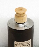
Here is a picture of a pulley I made recently from a section of maple dowel (for 600rpm operation using a flat belt) using the motor itself as a lathe.
It is not perfect, but better (truer) than what my local machinist could make. It is certainly good enough to get one going on the project, and make some tests or initial listening.
I'm just putting this up here for encouragement.
Dropbox - BLDC-pulley-maple.jpg
It is not perfect, but better (truer) than what my local machinist could make. It is certainly good enough to get one going on the project, and make some tests or initial listening.
I'm just putting this up here for encouragement.
Dropbox - BLDC-pulley-maple.jpg
I have "pully Envey"
Nice pully sir,
Just Goes to show that a pulley based on Pyramids design would be a real boon to lots of users in my poinion") - (not that i can say much as i dont have the abilitys to contribute)- but apart from the purchase of a VPI HRX pulley i dont see an alternative (local machinest in my area dont speak english and are mechanicaly a bit "rough")
- (not that i can say much as i dont have the abilitys to contribute)- but apart from the purchase of a VPI HRX pulley i dont see an alternative (local machinest in my area dont speak english and are mechanicaly a bit "rough")
what to do ?
Johnny
Nice pully sir,
Just Goes to show that a pulley based on Pyramids design would be a real boon to lots of users in my poinion
- (not that i can say much as i dont have the abilitys to contribute)- but apart from the purchase of a VPI HRX pulley i dont see an alternative (local machinest in my area dont speak english and are mechanicaly a bit "rough")what to do ?
Johnny
Here is my idea on how to use two belts with the sdp-si pulleys.
You can put one on top of another on the motor, glue them together and then cut the excess on top and adjust the final height.
I repeat that if you want to use only one belt the sdp-si pulleys are an exact fit to the motor and they ship anywhere.
You can put one on top of another on the motor, glue them together and then cut the excess on top and adjust the final height.
I repeat that if you want to use only one belt the sdp-si pulleys are an exact fit to the motor and they ship anywhere.
Attachments
![IMG_20171006_112900[1].jpg](/community/data/attachments/593/593273-0140ad2cf26bd40f4c55fe1db2ffc6cf.jpg)
International Shipping
I spoke with one of the sales reps at Anaheim Automation today and she said they could ship overseas via US Postal which will save a lot in shipping costs.
She sent a copy of their sales form, which only shows UPS and FedEx as shipping options, but said if the form was filled out with a note about using USPS as the carrier and sent to: sales@anaheimautomation.com, they could accommodate US Postal for shipping.
Hope this helps.
Attachments
I spoke with one of the sales reps at Anaheim Automation today and she said they could ship overseas via US Postal which will save a lot in shipping costs.
She sent a copy of their sales form, which only shows UPS and FedEx as shipping options, but said if the form was filled out with a note about using USPS as the carrier and sent to: sales@anaheimautomation.com, they could accommodate US Postal for shipping.
Hope this helps.
@Pyramid, thank you for your efforts.
Would you be able to let us know the name of this sales rep? I have spoken to two different reps (both male) at Anaheim, with little luck.
Perhaps speaking to the same person you did will yield some results.
Thanks!
PM Sent.
The sales person requested that their information not be posted on a public blog.
Please try sending the form to sales@anaheimautomation.com and specifically request US Postal as a shipping option. They will send a reply within a day or so.
The sales person requested that their information not be posted on a public blog.
Please try sending the form to sales@anaheimautomation.com and specifically request US Postal as a shipping option. They will send a reply within a day or so.
I am tempted to use the SG4, the MA-3D and the AA BLWS231S-24-2000 motor on a Thorens TD-125 to replace both, the original motor and electronics. The motor would need to run around 300RPM (as opposed to 600RPM people are using it here). Then I could use a pulley with a comparable diameter as the original (18.7mm with a 160mm sub-platter, flat belt). Would this combo work at 300RPM? Would the torque be enough? Is the motor still quiet at 300RPM?
Last edited:
I am tempted to use the SG4, the MA-3D and the AA BLWS231S-24-2000 motor on a Thorens TD-125 to replace both, the original motor and electronics. The motor would need to run around 300RPM (as opposed to 600RPM people are using it here). Then I could use a pulley with a comparable diameter as the original (18.7mm with a 160mm sub-platter, flat belt). Would this combo work at 300RPM? Would the torque be enough? Is the motor still quiet at 300RPM?
The BLWS series will run at 300 RPM but the frequency is 10Hz. If you use the BLWR series, the frequency is 20Hz for 300 RPM.
There really is no advantage to running the motor at 300 RPM. It will have plenty of torque and run very quiet at either speed. If it were me, I would run the motor at 600 RPM.
Help required with MA3D voltages at phase outputs
Hi gents ( and Pyramid)
I have an issue when trying to get the 3 correct voltages at the phase outputs during phase adjustments on the MA3D PCB.
Please admonish me if. Am reading the circuit diagram wrong ( likely!)
My fluke voltmeter says its a true RMS voltmeter.
I seem only to get 5 volts at the 3 phase voltage adjustment pots test points ( between ground on connector P6 and the appropate amp output) .., and can't adjust it ( that's 5 volts DC...nothing on AC!)....then I noticed , where I should be supplying 15 volts to P 1 on the MA3D I find 11.5 volts comeing from my PSU, that's all I can get out of it ( it is adjustable), now I understand I would require at least 15 volts to give enough headroom to the 12 regulator on the MA3D PCB, but according to the circuit diagram the 12 volt output of the regulator goes to the connector P2 which feeds the SG4, which in turn regulates that to 5 volts, there is no issue with this in my setup, the SG4 functions normally.
Am I correct in thinking the MA3D PCB must have 15 volts fed in as this voltage is fed to U 1and U2 ( via L1)..as opposed to the 11.5 volts I can squeeze out of my adjustable PSU? ( which is counter intuitive as how can my 11.5 volts turn on the 12V reg to supply connector P2...which in turn feed the sine wave gen which works normaly in this set up?
Prior to looking at the circuit diagram i thought it may be possible to supply my 11.5 volts in leu of the expected 15 volts by bypassing the 12V voltage regulator-- but this regulator appears to have influence on the MA3D (apart from supplying 12v to connector P2 ) as the required 15 volts supplied from P1 directly supply's U1 and U .....so must I replace my 11.5 volt supply with a 15 volt one?....or am I crap at reading circuit diagrams?
Sorry for long post..don't know any other way to describe it!..off for a milky drink and a lie down in a dark room!
Cheers lads
Johnny
Hi gents ( and Pyramid
)I have an issue when trying to get the 3 correct voltages at the phase outputs during phase adjustments on the MA3D PCB.
Please admonish me if. Am reading the circuit diagram wrong ( likely!)
My fluke voltmeter says its a true RMS voltmeter.
I seem only to get 5 volts at the 3 phase voltage adjustment pots test points ( between ground on connector P6 and the appropate amp output) .., and can't adjust it ( that's 5 volts DC...nothing on AC!)....then I noticed , where I should be supplying 15 volts to P 1 on the MA3D I find 11.5 volts comeing from my PSU, that's all I can get out of it ( it is adjustable), now I understand I would require at least 15 volts to give enough headroom to the 12 regulator on the MA3D PCB, but according to the circuit diagram the 12 volt output of the regulator goes to the connector P2 which feeds the SG4, which in turn regulates that to 5 volts, there is no issue with this in my setup, the SG4 functions normally.
Am I correct in thinking the MA3D PCB must have 15 volts fed in as this voltage is fed to U 1and U2 ( via L1)..as opposed to the 11.5 volts I can squeeze out of my adjustable PSU? ( which is counter intuitive as how can my 11.5 volts turn on the 12V reg to supply connector P2...which in turn feed the sine wave gen which works normaly in this set up?
Prior to looking at the circuit diagram i thought it may be possible to supply my 11.5 volts in leu of the expected 15 volts by bypassing the 12V voltage regulator-- but this regulator appears to have influence on the MA3D (apart from supplying 12v to connector P2 ) as the required 15 volts supplied from P1 directly supply's U1 and U .....so must I replace my 11.5 volt supply with a 15 volt one?....or am I crap at reading circuit diagrams?
Sorry for long post..don't know any other way to describe it!..off for a milky drink and a lie down in a dark room!
Cheers lads
Johnny
Johnny-
Yes, you need to supply 15VDC to the MA-3D. The chips must be able to generate 12VPP output and will not be able to do that with 11.5V or less input.
The TPA-3125 chips will work down to 10V, but you should run the PCB at the design voltage (15V). The alignment voltage is RMS so use the AC mode of your DVM. You should read the AC volts between each output and ground. (not TP1). TP1 is for balancing the outputs by getting the AC voltage between TP1 and ground as close to zero as possible.
Can you post a pic of your PCB?
The SG4 has a 5V regulator which will work down to ~7VDC input; after that, it will go out of regulation. That is what is happening with the 12V regulator on the MA-3D board. It will work down to ~14VDC input; anything below that and it will not regulate at 12V. With 11.5V input, you will probably get ~9.5VDC unregulated output.
Last edited:
Hi Pyramid
Hi sir,
Well..I will send a picture tomorrow as I don't own a smart phone or a digital camera ...my sons got a iPod, I'll use that!
I have applied 15 volts by borrowing a bench PSU, no change, on the PCB all tants are correctl orientated as are the electrolytic ( and both IC correctly orientated)
, I started with a factory default, set to high voltage mode / 128 and all 3 phases set to 0.
I measure about 7 .25 volts DC and nothing on AC, at motor test points ( other lead on 0 v ) however I notice my AC voltmeter has just died!! ( battery is ok) so perhaps I am being misled by my deceased fluke??.....I will have to go to work tomorrow and flèche another,
Switching to 33 or 45 rpm doesn't make a difference so it may point back to me voltmeter ( because it all worked last week when I bench tested with a computer PSU..that is to say all voltages set up correctly, and 33/45 switch adjusted when switch flicked.
May point to my voltmeter or o/p form sine wave gen?..will post picture and test with another voltmeter tomorrow ( it's 5 am here!)
Glad to proved wrong if it's that bloody voltmeter, thanks pyramid, will post later
Regards
Johnny
wildo sir
Hi again good sir,..My thanks.
Am in the process of trying to borrow (steal!) a True RMS volt meter at work, i found a LM 9015 + 15 Volt reg and a sutabely spunky transformer (+12v ) in the bottom of my "treasure box"..so ill install that and do those voltage checks you recomended , It gives 18.6 volts after rectfication...should work with the 15 volt voltage reg i just fitted, thank you again, i will percevere (or however you spell it!)
let you know boss.
regards
johnny
(bet its something real basic)
Hi again good sir,..My thanks.
Am in the process of trying to borrow (steal!) a True RMS volt meter at work, i found a LM 9015 + 15 Volt reg and a sutabely spunky transformer (+12v ) in the bottom of my "treasure box"..so ill install that and do those voltage checks you recomended , It gives 18.6 volts after rectfication...should work with the 15 volt voltage reg i just fitted, thank you again, i will percevere (or however you spell it!)
let you know boss.
regards
johnny
(bet its something real basic
)There really is no advantage to running the motor at 300 RPM. It will have plenty of torque and run very quiet at either speed. If it were me, I would run the motor at 600 RPM.
I was concerned that by lowering the pulley diameter to about half (0.375") for 600 RPM, the surface contact area with the belt will also be much less, and this may cause belt slip. Is this something to consider?
It depends on the thickness and stiffness of the belt. A thin flat belt would be less of a problem than a thick round one. Also, is there a way to adjust tension?
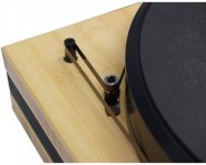
I always liked the solution used in the Artemis SA1 turntable. They used a flat belt and a tensioner to keep constant force on the belt. The attached picture is taken from an article about the SA1 in Positive Feedback magazine. artemis labs sa1
Anyone have good leads on where to buy hardware to make a diy tensioner?
Thanks,
---Gary
Attachments
- Home
- Source & Line
- Analogue Source
- 3 Phase Class D amp for DIY BLDC motor Drive