About a dual power supply giving +Vs and -Vs from 2 secondary windings with common ground and 2 diodes to Vs+ and 2 diodes to Vs-.
What is best to feed a Class B power amp ?
Should one:
1 Twist the +Vs wire with a ground wire and the -Vs wire with a ground wire ?
2 Twist the +Vs wire with the -Vs wire ? then what about ground wire(s) ?
The idea of twisting is to make current loops of a minimum areas, so as to launch stray fields as little as possible.
May be the answer depends wether:
There is the same draw at plus and minus as in a class B amp
Or
The draw at Vs+ is not equal as the draw at Vs-.
Case 1: the Class-B power amp PCB includes significant amounts of filter capacitance between +Vs and GND (also between -Vs and GND)
Case 2: the Class-B power amp PCB does not include significant filter capacitors between +Vs and GND (or between -Vs and GND)
Perhaps the answers are different for Case 1 and Case 2.
Case 2: the Class-B power amp PCB does not include significant filter capacitors between +Vs and GND (or between -Vs and GND)
Perhaps the answers are different for Case 1 and Case 2.
I better not move that stuff on my ways back and forth in Queensland.In Australia, however, you twist in the opposite direction.
The idea of twisting is to make current loops of a minimum areas, so as to launch stray fields as little as possible.
It also cancels picked up emi
I doubt it can pick much emi because of the low impedance of windings, electrolytic caps and hf caps.It also cancels picked up emi
On the other hand, I am sure it can launch much emi because instantaneous currents are huge when diodes as conducting ( for a short time in the periods of the power mains ).
Last edited:
The current through the ground wire of the PSU is never zero.
When the PSU has a common ground for both power rails you should twist V+, V- and ground together.
Don't connect the speaker return at the PSU, better to connect it close to where the feedback connects to ground on the amp board.
When the PSU has a common ground for both power rails you should twist V+, V- and ground together.
Don't connect the speaker return at the PSU, better to connect it close to where the feedback connects to ground on the amp board.
I know, there are people who connect the speaker ground at the PSU. I think it is wrong, it should be connected at the amp PCB as close as possible to the HF decoupling caps of the output transistors.
Can you point the case( s ), there is current in the ground wire. I think it can only occur from an unbalance between the plus and the minus circuits. ( kind of a three phase electric power )
Can you point the case( s ), there is current in the ground wire. I think it can only occur from an unbalance between the plus and the minus circuits. ( kind of a three phase electric power )
The current through the ground wire of the PSU is never zero.
When the PSU has a common ground for both power rails you should twist V+, V- and ground together.
I see when there is current through the ground wire: Mostly when the audio signal is bass, near and under 50Hz, little when the audio is highs well over 50 Hz.
Am afraid, I opened a can of worms.
There are two related issues here:
1. identify the current loop through the speaker, output stage and PSU and keep the loop area small by keeping the relevant wires close together and twisted
2. identify the correct voltage reference point for the amplifier input, output and feedback and ensure that any wire from here is kept well away from the above wires
Alternatively, just use a star ground and hope for the best.
That is the question....How ?There are two related issues here:
1. identify the current loop through the speaker, output stage and PSU and keep the loop area small by keeping the relevant wires close together and twisted
This brings another question....How to implement signal ground, power ground and chassis ground ? if not, all confused at a star ground.2. identify the correct voltage reference point for the amplifier input, output and feedback and ensure that any wire from here is kept well away from the above wires
Alternatively, just use a star ground and hope for the best.
A small question inside: With an input via an RCA plug, is the RCA ground at chassis ground OR the RCA ground isolated from chassis and connected to signal ground ?
As I said "identify the current loop". This is part of circuit design. If you cannot do this then you cannot design the circuit. If you are using someone else's circuit then you have to hope that he has done this properly and said what it is.
There are lots of threads with lots of information on grounding. Some of it is helpful. No point in repeating it all here again. I only raised the issue because someone might be tempted to twist a ground reference wire with an output current loop wire and so induce interference into what is supposed to be a clean ground.
There are lots of threads with lots of information on grounding. Some of it is helpful. No point in repeating it all here again. I only raised the issue because someone might be tempted to twist a ground reference wire with an output current loop wire and so induce interference into what is supposed to be a clean ground.
The current loops are identified, I did so well before my original post.
Grounding is rehashed all over the net, mostly smart handwaving,with contradictions that show up only when going fully in depth into it.
Unique Star ground.
Multiple: Signal ground Power ground Chassis ground.....and they end up connected together.
My OP is an attempt to find real answers.
So far, we are running in circles.
Let me begin a solution attempt.
My amp is a unity gain output stage with an op-amp as a front end and massive feedback over these.
The power ground is mostly where the two HF caps that decouple the power transistors Vs+ and Vs- meet, secondly where the two revervoir caps on the amp pcb meet next to it.
The loud speaker ground wire and the PSU ground wire go at this power ground.
The signal ground is mostly where the HF caps that decouple the Vs+ and Vs- of the op-amp, secondly where the two associeted electrolytic caps meet next to it.
The feed back network ( I use non inverting mode ) and the input signal ground wire go at this signal ground.
The power ground and the signal ground are linked by a unique link on the amp pcb.
As can be seen the output signal is not exactly the amplified input signal, it is skewed by a possible difference between signal ground and power ground.
Chassis is tied to the mains power ground prong.
Chassis is linked by a unique wire at the power ground wire ( PSU side ) at the PSU reservoir caps.
If that link carries no current and has no magnetic fields coupling to it then you are OK.The power ground and the signal ground are linked by a unique link on the amp pcb.
As can be seen the output signal is not exactly the amplified input signal, it is skewed by a possible difference between signal ground and power ground.
I am investigating on the current thru this link and return loops. I do not see clearly, yet, I think I need to reorganize my LTspice simulation to clearly split the part referenced at the power ground and the part referenced at the signal ground; Hopefully, I will identify and trace currents between these two parts.
No.The current in the ground wire is zero in the case of a perfectly symmetrical PS and Class B amp.
So #2 should be best, but I am not sure....
Look at your ouput stage and think only of an LF bass note that transistions slowly into one half wave and then crosses over into the other half wave.
Now thinking about that, look at the current flowing from the +ve supply into the output stage, to the speaker and finally returning to the PSU.
Now consider the other half wave of that LF tone.
Consider the current flowing from (to) the -ve supply into (out of) the output stage, to (from) the speaker and finally returning to the PSU.
In BOTH of the above cases the returning current passes along the Zero Volts line back to the PSU. The current MUST return to it's Source. The source of the speaker current is the PSU capacitor/s
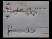
Draw a simplyfied PSU + amp + spkr Load (use an opamp symbol for the amp)
Draw in coloured pencil the ROUTE the current must take to get from the PSU capacitor to the speaker and use another colour for the Return current.
Note that the current for each halfwave uses only two wires of the twisted triplet to pass energy to the speaker.
Note also that the Zero Volts wire carries current for the WHOLE waveform.
Finally note that each pair of current carrying wires need to be close coupled to minimise EMI.
Sketch to be attached when the camera battery has charged.
Attachments
Last edited:
- Status
- This old topic is closed. If you want to reopen this topic, contact a moderator using the "Report Post" button.
- Home
- Amplifiers
- Power Supplies
- Let's twist again.