DC coupling saves you the cost and coloration of the coupling capacitor(s),
It exposes the system to turn on / turn off dc transients so you need a mute delay circuit. A faulty component can cause DC offset so ideally you want a dc protect circuit to operate the output relay. You'll need positive and negative power supply and regulators, and hard to find negative path jfets. You'll need dual devices or thermally tracking input pairs and/or a dc servo to track offset changes
A lot of extra work and cost, but worth it to some of us.
Ticknpop thanks for explaining. The design I see including the Feucht paper is to use a dual supply. I know the alternate design B1 using complementary Jfet to avoid DC blocking capacitor.
I was trying to figure out why most designs with Jfet buffer including the one one post #1 uses dual supply while B1 seems like uses a single supply.
I was trying to figure out why most designs with Jfet buffer including the one one post #1 uses dual supply while B1 seems like uses a single supply.
Pico, I was thinking bipolar supply would add more, or at least that is what I understood. Please explain a bit more where can I save on components .
I am looking for a zener based bipolar supply elsewhere.
Have a look at the original B1 and do a parts count.
Not all of the parts are necessary but many are.
Pico, I was thinking bipolar supply would add more, or at least that is what I understood. Please explain a bit more where can I save on components .
I am looking for a zener based bipolar supply elsewhere.
You just save on signal path components. Polypropylene coupling capacitors specifically.
You can use LM317/337 PSUs. Some people like to go the whole way with PSUs though.
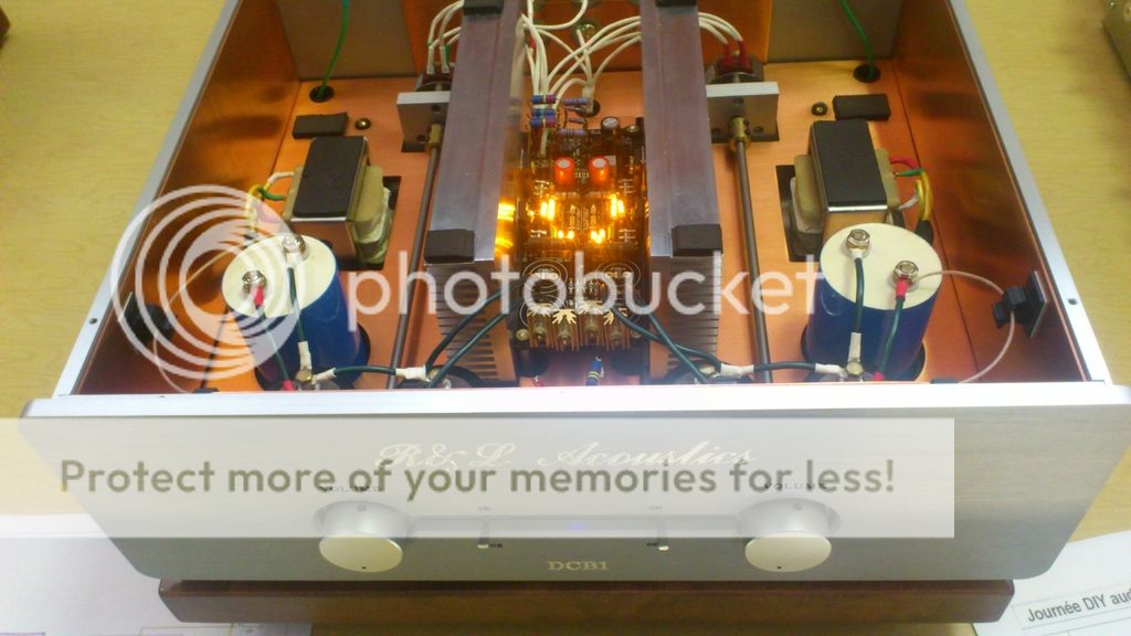
Here's a beautiful DCB1 & Hot-Rod shunt PSUs example by Canadian member Scorpion.
Salas, thanks for chiming in.I was under the impression LM317 is the noisiest. Of course two Reflektors will be perfect for power supply. I thought a zener emitter follower will help in terms of reducing PCB size and will have a middle ground in terms of PS noise. I am making these inferences based on this
Simple Voltage Regulators Part 1: Noise - [English]
There is a thread I started in power supply asking for design help. May be you can help me out with some recommendations ( extremely valuable)")
Zener+Voltage follower
Simple Voltage Regulators Part 1: Noise - [English]
There is a thread I started in power supply asking for design help. May be you can help me out with some recommendations ( extremely valuable)
Zener+Voltage follower
Last edited:
- Status
- This old topic is closed. If you want to reopen this topic, contact a moderator using the "Report Post" button.
- Home
- Amplifiers
- Pass Labs
- Another B1 design