Thanks Zen Mod. But confused, the two circuits look quite different to me. I like the B1, because it uses 2 * LSK170 (roughly matched) per channel which is cheaper than a complementary pair. Not sure about that 1k resistor on the output though. Won't that considerably increase the output impedance and for what? And B1 v2, what's that? Have you got a link please? Thanks very much if you can answer.
there was two B1 iterations ;
first one , with two 2SK170
second one , with 2SK170+2SJ74 , practically the same as FE of M2
later one is having double cojones vs. former one , with better THD spectra - overal smaller THD but still enough difference between two sexes , to still have 2nd dominant over 3rd harmonic
dunno where you can find more info ...... scattered somewhere in forum ..... maybe in B1 thread
you don't need that 1K on output of buffer ..... Papa put it there from idiotproof reasons
OK Zen, that explains things a lot. Probably best to build M2 as is then. I'll have a hunt for that v2 out of interest.
Cheers, cyril
Hi Cyril,
This thread contains info on the B1 v2:
http://www.diyaudio.com/forums/pass-labs/301812-b1-rev-2-a.html
Cheers,
Dennis
Hello ZM
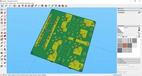
if you´re starting with ECAD to MCAD export, I´ll suggest to use EAGLE IDF export (all ECAD tools export IDF) and FreeCAD with MCAD PCB plugin (you´re using 3D STEP models directly, only X,Y,Z mapping is boring). It´s simply professionally (IDF to SolidWorks) with STEP modelling and not MESH modelling.
Here the Link for SketchUP: https://eagleup.wordpress.com/
For the models: I´m using 3dcontentcentral (or manufacturer) for STEP/IGS models; then FreeCAD to STL conversion; then STL to COLLADA using Blender; finally importing COLLADA into SketchUP.
Don´t forget, you´re working in meter!
JP
Hello ZM
if you´re starting with ECAD to MCAD export, I´ll suggest to use EAGLE IDF export (all ECAD tools export IDF) and FreeCAD with MCAD PCB plugin (you´re using 3D STEP models directly, only X,Y,Z mapping is boring). It´s simply professionally (IDF to SolidWorks) with STEP modelling and not MESH modelling.
Here the Link for SketchUP: https://eagleup.wordpress.com/
For the models: I´m using 3dcontentcentral (or manufacturer) for STEP/IGS models; then FreeCAD to STL conversion; then STL to COLLADA using Blender; finally importing COLLADA into SketchUP.
Don´t forget, you´re working in meter!
JP
Vielen Dank!
I think I'm going to stay in 2D

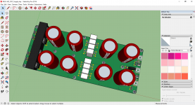
Most amp cases are tight on length but not width.as promised...
JP
To reduce the length it's preferable to run the caps on each side of the R horizontally.
I can provide a picture if necessary..

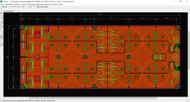
Next attempt.
Dual common cathode TO220 or TO247 diode.
Fischer Elektronik SK492 heatsink with THFU clamp.
Shunt realized with mounting ept 911-32006 power terminals.
Faston or wired cable connection.
JP
Dual common cathode TO220 or TO247 diode.
Fischer Elektronik SK492 heatsink with THFU clamp.
Shunt realized with mounting ept 911-32006 power terminals.
Faston or wired cable connection.
JP
Attachments
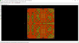
Next attempt.
Dual common cathode TO220 or TO247 diode.
Fischer Elektronik SK492 heatsink with THFU clamp.
Shunt realized with mounting ept 911-32006 power terminals.
Faston or wired cable connection.
JP
Here is an example
Vishay - Diodes and Rectifiers - VS-HFA50PA60CHN3 - HEXFRED® Ultrafast Soft Recovery Diode, 2 x 25 A
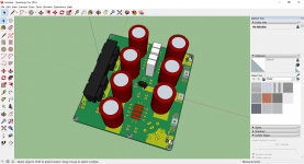
Next attempt.
Dual common cathode TO220 or TO247 diode.
Fischer Elektronik SK492 heatsink with THFU clamp.
Shunt realized with mounting ept 911-32006 power terminals.
Faston or wired cable connection.
JP
This is looking extremely nice.
- Home
- Amplifiers
- Pass Labs
- Official M2 schematic