For those DIYers overseas and having difficulty getting AA motors (or they are cost prohibitive, you could try these motors from Alibaba:
This appears to be the same form factor as the BLWR series although I don't know what the shaft diameter is. They have power ratings from 10-60W; I wouldn't go higher than 10W with this controller.
https://www.alibaba.com/product-detail/high-efficiency-24V-30W-brushless-dc_60547562510.html?spm=a2700.7724838.0.0.ZVjPJ1
These two are the closest I could find to the BLWS series, but at least one of them has a 7.5mm shaft and is D shaped. Multiple power ratings as well, but the 9.6W motor is very similar to the AA.
https://www.alibaba.com/product-detail/hot-sale-diameter-57mm-24V-48V_60581144320.html?spm=a2700.7724838.0.0.vGeXPr
https://www.alibaba.com/product-detail/dc-motor-24v-brushless-motor-high_60552816421.html?spm=a2700.7724838.0.0.akHWO5
When in doubt about the specs, do a comparison with the data from AA's website.
Click on Go Advanced and then click on Manage attachments to upload the actual files from your PC. When you post links, they are probably password protected for your account at Google, that' s why you can see them.
None of the pics are on my PC. I take them all with my iPhone. I was trying to avoid having to transfer them all to the PC constantly by allowing the Google Photos App to upload them automatically. I tried using the URL attachment feature in the advanced section, but the links for the pictures all cause errors when I try to upload them. The only (partial?) success I seem to have had is by sharing the pictures on Google Photos and then navigating directly to the image page, copying its link and pasting it in my post with the add picture button. Sorry for the problems. I don't mean to derail the thread.
Since I have complete control over the phase of the 3 windings, I can also control the direction of rotation in software. I can easily switch between CW rotation for belt drive or by putting a rubber grommet on the pulley and switching to CCW...
As I've work my way into my BLDC motor project it has crossed my mind that trying a rim drive solution would make sense. Is there any possibility of accomplishing CCW rotation with the SG4?
Thanks Ralph...I was hoping that was the answer, since Bill stated he accomplished it through software I figured I would ask.
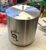
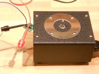
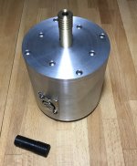
After a couple of weeks of working here and there I managed to finally work out the kinks in my motor housing. I had started it while waiting for the amp boards. It began life as a piece of 1/2" wall 4" diameter 6061 pipe I got at my local metal yards "Discount Barn" and some 5/16" plate scrap I had around.
I still have to finish up the pulley before I move on to the controller and amp. Figured I'd post a pic for fun. I'll probably post more of the fabrication process once I find time to start a thread about refurbishing/modifying my HW19.
Attachments
Hi everyone
Forgive me if I'm missing something, as I honestly didn't go in detail over the 21 pages of this thread...
Have you tried looking at radily available controllers for BLDC's ?
I like and use one from Nanotec (CL-3E). They support BLDC's and Stepper motors and offer full programmability over speed, torque, drive modes, ramp-up and ramp-down times.
They're programmable in C, are small and completely self contained. This model is probably powerful enough for most turntables, but more powerful ones exist.
Nanotec also has a big offering of BLDC's and encoders if needed.
Personally, I'm using this controller to drive a PM stepper motor to drive my new TT. Slightly more vibration, but plenty of torque and great speed accuracy, both in closed-loop or open-loop modes - i'm running in closed -loop.
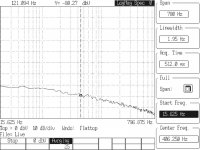
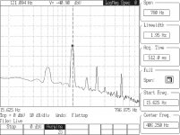
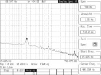
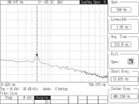
I picked up a 3 axis accelerometer from Analog Devices (ADXL327) which has a full scale reading of 2Gs. I bolted the sensor to both a Hurst 59 series 600 RPM AC motor and the AA BLWS series motor and did some tests using a Stanford Research SR770 dynamic signal analyzer. The two images named baseline are with the ADXL327 mounted to each motor but with the power switch to the motor off (Hurst) or with the SG4 in standby (BLWS).
When started, the Hurst motor audibly hummed at 120Hz; I could hear it, feel it and see it on a scope connected to the ADXL327 output. At 120Hz, the Hurst motor was almost 40dB above the baseline. There were also significant responses at 180Hz, 240Hz and 480Hz.
When the BLWS motor was started, I could not feel any vibration and there was barely a perceptible difference on the SR770 between baseline and motor on. The BLWS series has a response at 60Hz, but it is the same as with the motor off (most likely leakage from the power supply). At 120Hz, the BLWS motor is ~35dB quieter than the Hurst (~31x). The BLWS motor was not mounted in any case; if it were, it would run even quieter.
Attachments
Last edited:
Wow, that's some very good quantitative results! Did you measure along a radial direction (x or y) or axial (z, along the spindle direction)?
If you're interested, I can send you an ADXL345 breakout board that outputs digitally using I2C or SPI. Don't know if it's necessary given the results you achieved however.
If you're interested, I can send you an ADXL345 breakout board that outputs digitally using I2C or SPI. Don't know if it's necessary given the results you achieved however.
I was connected to the Y axis output. X axis looked to be nearly identical, Z axis was similar in frequency but lower amplitude.
I prefer the analog output sensor. I was going to build a summing circuit that would add all 3 outputs, but the X-Y seem to be closely correlated. Using op-amps, I can also reduce the noise (but also the BW). With the factory LPF filter caps, the BW is ~700Hz.
I prefer the analog output sensor. I was going to build a summing circuit that would add all 3 outputs, but the X-Y seem to be closely correlated. Using op-amps, I can also reduce the noise (but also the BW). With the factory LPF filter caps, the BW is ~700Hz.
That's good that the x and y are nearly identical.*It's what you'd expect based on the physical symmetry. I think you could make an argument to not measure y, and just double up the x number.
What are we most concerned with?* Vibrations radially or axially?* Vibrations through the belt, or through the motor mount?* I'm going to guess motor mount.
Analog vs digital: Fair enough.* But you can't do a simple summation.* Example: if Vx =1 and Vz = -1,* you don't want your answer to be 0.* I know that's not the range of the ADXL outputs, but it serves as an example of why.
I think at a minimum you need to take the absolute value of each axis. Or for a single RMS number, I think that's the definition: Sqrt( avg(x^2) + avg(y^2) + avg(z^2)). I think this gets rather complex with opamps, maybe some mfg makes a chip?
I'm sure you know all this, so I'm checking to see if I have it right and for others to see in case they're interested.
Thanks again for all the hard work!
I think the definition for RMS of a set of 3 values is:Sqrt ((x²+Y²+Z²)/3), but do we really need RMS values for the output? If we are only interested in a relative value for comparison, I don't think it is necessary (if we're trying to compute an absolute RMS specification value, then yes). Actually, I think this could be accomplished using opamp multiplier circuits, but it may not be necessary.
I hadn't considered the phase of the 3 signals but of course it will be necessary and it is easy to construct an ABS value function using opamps, as well as LPFs and summing circuits. I think a 3 axis result will be more meaningful (and accurate) than a single output. Thanks for pointing this out.
I hadn't considered the phase of the 3 signals but of course it will be necessary and it is easy to construct an ABS value function using opamps, as well as LPFs and summing circuits. I think a 3 axis result will be more meaningful (and accurate) than a single output. Thanks for pointing this out.
Ah, the light bulb goes on. I was thinking about a different, and a lot less useful, set of measurements. I was think of looking at vibration as a function of motor rpm. RMS values would be appropriate there i believe.
While I think that would be interesting, it's kind of moot since you cant pick a speed. Your platter needs what it needs (assuming you're not swapping out pulleys)
While I think that would be interesting, it's kind of moot since you cant pick a speed. Your platter needs what it needs (assuming you're not swapping out pulleys)
I've ordered up an identical accelerometer to see what the level of vibration is for a Papst 3 phase motor and my BLDC motors as a comparison. I guess to make a valid comparison I will need to match the test setups as closely as possible. Any thoughts on the best way to do this?
I would just make sure the sensor PCB is firmly mounted to the motor chassis in each case. Don't use double sided tape or anything that will isolate or dampen the vibration.
I used a 3V bench top supply to power the ADXL327; a battery powered supply may be better and reduce any 60Hz signal from affecting the output.
I'd like to get my hands on a VPI Classic table and measure how much of the motor vibration is getting into the plinth (I've read where they were having problems with this, but apparently it was caused by UPS and shipping damage). The AA motor should fit in the same mounting holes, although the flange is thicker; I think it will still be a drop in replacement. I guess I could always use the cartridge on a stationary platter (motor running, no belt) to measure the response.
It's nice to see some data supporting the desired outcome.
I'm still plugging away at the mechanical end of things. I believe I was able to come up with a usable pulley for my application. I had more than one hurdle along the way with the machining.
My first attempt is lying on the table next to the motor assembly. It was done in Delrin. I found machining Delrin pretty straight forward. It definitely has an elasticity to it, so your tools need to be sharp.
I was able to get a usable bore in it starting with a 1/4" centering bit and then finishing with a drill the same size mounted in my tail stock. The material seems to stretch around the drill slightly. This actually worked to my benefit as it created an interference fit with the shaft on the motor that resulted in absolutely no play.
The problem with this pulley was that once I mounted it on the motor and tested run-out with my dial gauge turning it by hand it was unacceptable. For some reason it was not concentric and wobbling off center by .003-.004. After taking some measurements again with my calipers, I realized that the pulley was tapered slightly, but couldn't figure out why. It took me awhile to discover that my tail stock was ever so slightly out of alignment and this was causing the taper of the pulley exterior and also distorting the bore during drilling. I adjusted the tail stock and dialed things in properly by making several passes on a piece of brass stock and retaking measurements with my dial gauge and calipers until I got a straight cut.
Since I already had the brass in the lathe and it was close to the size I needed, I decided to use it for the next attempt. I started the bore in the same manner with my centering bit, although not all the way through the piece at first as my goal was to turn it between centers to get the entire length truely concentric. That was a mistake. As I had to go back to finish boring it in the chuck later on and I felt it was being held ever so slightly different. The full length of the stock should have been bored first and then the exterior turned to size between centers and the belt grooves cut.
I got a pulley out of the brass that is just snug and slightly resistant to going onto the motor shaft. Drilling the set screw holes and tapping them was pretty straight forward on my mill.
Mounted on the motor and clamped in place I managed to achieve about a .0005 tolerance for its rotation at the very tip of the pulley. This pulley is 1.5" tall in order to meet my needs of placing it under the HW19 plinth that I am modifying.
I think I may be able to improve on the outcome and might take another shot at it in Delrin as I preferred the fit to the motor shaft even though it took effort to mount and required a heat gun to expand and remove. Boring it full length first will probably help with that as there won't be issues with air being compressed or vacuum during installation and removal.
Attachments
If it were mine, I would find a way to grind it down while mounted and running ( I own a lathe also )
Not an easy affair, but you are so close in tolerance that it wouldn,t take much to make it work out. Just think it thru on how you would mount it
If I go this route I would enlarge the pulley in a stepped affair for a little flywheel effect
Brass stock is cheap.
Regards
David
Not an easy affair, but you are so close in tolerance that it wouldn,t take much to make it work out. Just think it thru on how you would mount it
If I go this route I would enlarge the pulley in a stepped affair for a little flywheel effect
Brass stock is cheap.
Regards
David
You can get drill rod cheap. Jig it up in 5c collet and machine to shaft size. Check to see you have run out to a minimum. Fast and super light cuts. You can use a 3 set screw pulley or loctite 609 to secure the pulley to the rod. Then high speed super light cuts. You can file a flat on the rod so the set screws hold better.
Enjoy Tom
Enjoy Tom
- Home
- Source & Line
- Analogue Source
- 3 Phase BLDC motor for turntable use?