> I want to stick to this 1973 RCA schematic.... published in one of RCA's last vacuum tube manuals, I think it represents the state of the art of the seventies. (This is not a sixties design). ...I have some confidence in the RCA engineers of yesterday.
I am son of an RCA engineer of that period. I have less confidence. RCA had some good engineers but the company was going dysfunctional. (For one thing, laying-off good engineers left and right.)
Also RCA was rarely known for "good sound". They did have Olsen and a few of his driver/cabinet designs were good (he did a lot of commercial crap also). RCA sold a LOT of broadcast, film, and recording gear, and one or two of those products have cult-followings, but a lot of it is mediocre.
That said-- audio ideas in general are not very interesting to The Company (with rare exceptions like THAT Corp). RCA was more interested in dead-end radar and computer contracts, with a lot of cheap TV sets on the side. It _is_ likely this plan was some engineer's home-brew project, and they drew it up to fluff-out the back pages of the RC manual.
> I think it represents the state of the art of the seventies. (This is not a sixties design).
It appears in RC-20, 1960.
http://www.nj7p.org/Manuals/PDFs/Tubes/RCA-RC-20-1960.pdf
There is more detail in RC-24 and I will attach a snip of that one.
A super-similar plan appears in RC-19 1959-- same idea with a less elaborate power supply (cap-input, no G2 regulator).
http://www.nj7p.org/Manuals/PDFs/Tubes/RCA-RC-19-1959.pdf
I'd suspect it is the same home-brew, upgraded 1959-1960.
I think it "sells tubes". That is a LOT of tubes for 50 Watts. And high-profit tubes, 7199 7027 and even the 6CB6. To the tube sales manager, this is a Good Thing. I don't think it was *designed* to sell more tubes; more like, engineers got tubes cheap or free, so using another tube on a whim was no big deal.
Attachments
My Dutch is not too good, but 6BX6/EF80 looks similar to 6CB6 and gets used for audio. Great promise.
Should pass the microphonics test.
http://tubedata.milbert.com/sheets/093/6/6CB6A.pdf
http://tubedata.milbert.com/sheets/082/e/EF80.pdf
http://tubedata.milbert.com/sheets/168/7/7199.pdf
----
The RCA 50 Watt amplifier design has been somewhat enigmatic to me for some time.
With three N Fdbk loops (2 nested ones, and one outer Global), the Schade like loop to the 6CB6 plate lowers the gain greatly for the loop to the 6CB6 cathode (by loading down the hi-Z 6CB6 plate). While the loop to the cathode is far more effective at reducing distortion.
Seems a waste of the cathode loop. However, it does linearize the V to I conversion of the 6CB6, for the "Schade" loop up top, so it's hard to judge the overall effects. But by lowering the high loop gain for the 6CB6 cathode loop, it is probably far more stable for DIY efforts being successful. This may be the reason it's that way, I don't know.
Joe Rasmussen in the thread "Modern Tube Amplifier Designs?" post #135 April 2007 mentions some experimenting with the two local loop types.
http://www.diyaudio.com/forums/tubes-valves/142246-modern-tube-amplifier-designs-14.html#post1809142
"the Anode-to-Anode (AA) loop pair was tried on its own and while it sort of worked it was also problematic in a different way. There was a great sense of clarity but also tended to sound lightish in balance. The the Anode-to-Source (AS [6CB6 cathode here]) loop pair was introduced and this had the exact opposite effect. If AS was balanced against AA, then the balance could be "dialled" in. If AS was allowed to dominate, then the sound would sound to rich and too dark and taking out AA alltogether and it would sound positively weird. "
[ Hmmm, maybe removing the anode to anode AA loop left a frequency sensitive too Hi-Z drive?]
(Not exactly "technical" interpretations, and using a JFET/tube cascode instead of a pentode driver) But he said it was possible to balance the two loops for best results. Is the RCA design balanced by these criteria somehow?
Then, I have also heard the RCA 50 Watt design described as boring, non musical. (ie, probably low distortion). Blameless maybe. Probably depends on who is listening.
Last edited:
PRR, can i ask you, what constitute a very good tube amp design at this level power?
Of course, my Pyramid!
")
Attachments
Yes, i found that design interesting too. <snip>
Hi Mona... any subsitute for 6CM8.... thanks!
Zekk
what constitute a very good tube amp design at this level power?
At the PP 6L6GC power level, the H/K Cit. 5 is certainly a good candidate starting point. It's a "Super/Duper" implementation of Mullard style circuitry. Stu Hegeman & Co. focused on high gm in the small signal circuitry.
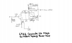
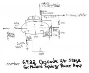
The 12BY7 used as the voltage amplifier is getting scarce and (IMO) is best reserved for existing units. I've uploaded a 6922 cascode, which is specifically designed to replace that 12BY7. Additional tweaks to the H/K original are CCS loading the LTP tail and replacing the 6CG7 with an ECC99. Embellish the high gm theme.
Attachments
Not that i now off.The 6CM8 has a pentode like the 6CB6Hi Mona... any subsitute for 6CM8.... thanks!
Zekk
and a triode like the 12AX7.
It's a stock item at Frag Jan zuerst- Ask Jan first: Roehren und mehr
not expensive, 4€18 tax in.
Mona
Why not doing like this ?The 12BY7 used as the voltage amplifier is getting scarce and (IMO) is best reserved for existing units. I've uploaded a 6922 cascode, which is specifically designed to replace that 12BY7.
Automatic (even) partitioning of the voltage over the triodes.
Current depends only on the cathode resistor (and supply)
Probably no need for a regulated supply.
Mona
Attachments
I think in that era all tube amps was called Hi-Fi.You might get disappointed with it: just because someone titled the schematics "50 Wa Hi-Fi" - it's the last winter's snow )<snip>
Strange, that era was the golden age of tube amplifiers.
Some designs from that era still outperform most of the "modern day" gear.
Everything to be known about amplifiers was allready discovered by then.
The 7027A output tube was specially designed for audio.
And no, I will not buy Japanese "boutique" transformers, I will use the Hammonds.
All tubes I acquired allready years ago, so no problem there.
And I really want to see the nice glow of the stabilizer tube!
Best regards, 968driver.
What lamination the Hammond OPTs use?Strange, that era was the golden age of tube amplifiers.
<snip>
Type/gauge etc?
689driver,
It might appear that many of us are trying to rubbish this design; but (for me, at least) that is not so. One is simply pointing to fresher ideas. But let us then stick with this design. There are unfortunately several errors (with due respect to RCA) that do need pointing out (as can happen to the best of firms ....). You did invite comment:
Firstly, 600Vrms for the h.t. transformer. The 5R4 is a directly heated rectifier which will supply voltage some 20 sec. before the rest of the tubes have heated up. That delivers all of 848Vp momentary to C10 - a 450V capacitor! It is true that good electrolytic caps can stand overvoltage for a short time, but almost twice the rated value ... I don't think so. Then the circuit itself sees 460V before L1; that is taken as under operating conditions. That still puts C10 operating at theoretically its maximum. Should the line inrut rise slightly .....
Regarding this point then it is mandatory that two series caps of some 450V each with the necessary dividing resistors be used here.
The next point is rather more difficult to explain in a sentence or two. For classic pentode operation the screen grid is decoupled to the cathode.
Here the decoupling cap C2 goes directly to ground, but the cathode is not ground. With global NFB here is in fact quite some signal voltage between G2 and cathode here. The correct connection for C2 would be from screen (pin 3) to cathode (pin 6). You will notice that the input stage for the two previous amplifiers in the tube manual [designs 27-9 and 27-10) is identical; there it is done correctly (as in the Mullard 5-20 et al)].
One thing I do notice which is missing in most pentode output stages and done correctly here, is to load the output with a finite resistor so as to avoid instability on accidental open load. In this design done by the feedback resistor R29 (820 ohms for 8 ohm load + R6 (10 ohm).
Hoping not to exceed my welcome: I would like to indicate that chancing incorrct connection of the gnfb phase if feedback is 'the wrong way round' and experiencing motorboating (note 3 on page 609, Tube Manual RC-27), is a dangerous way of determining correct feedback phase. That could easily destroy an output transformer or perhaps a tube because of voltage peaks. Safer is to first use an R29 of safe value (say 47K in this case) and without C7, and input a small signal. If touching R29 to the output shows a small output rise, the phase is the wrong way round.
Wishing you well with this!
Mr. Potgieter,
many thanks for your very constructive comments!
All this is very helpfull.
As for C10, the power supply smoothing capacitor, I allready had decided on two series connected capacitors with balancing resistors, the way you are suggesting.
Sure, I will also consider your other remarks, thanks again!
Normally I should have the amp completed before the end of this year.
I will keep everybody informed on the progress.
Best regards, 968driver.
Regarding the C2 bypass cap connection for the screen of the 7199 pentode, I would try it both ways. With either a listening test or FFT test on the PC.
Normally one does connect the screen bypass to the cathode, especially for power stages, but here the ground connection would provide a small ultralinear like N Fdbk effect for the input pentode (via cathode voltage swing). The pentode will have a small expansive 3/2 or 2.0 power law itself (only a small signal input range), so some local N Fdbk via the screen might be intentional. I'm guessing the designer was well versed in design tricks and may have selected what sounded or performed best. Easy enough to find out (make changes while powered off). Probably not a big deal.
------
Oh, on any of those substitute pentodes mentioned above, one should check the screen voltage versus the original tube for idle current. Might require some screen V adjustment to get optimum or identical idle current.
..
Last edited:
Probably no need for a regulated supply.
PSRR in cascodes is, essentially, non-existent. Therefore, extremely "clean" B+ is very much in order.
<snip>
Remaining close to the original, oine must remember that this circuit appeared in the 60's. UL was barely known then, as was not other alternatives. <snip>
Pretty common here in the U.S. and the U.K. by the mid 1950s. Acrosound from the very early 1950s (Keroes and Hafler claim to have invented it in 1948/1949, but it appears to have appeared in the UK around the same time or even earlier, sometimes referred to as partial triode) Dynaco from the mid 1950s used it in all models, the Citation II, not to mention the Mullard 5-20 design which Avantic, Leak and countless other UK companies cloned to some degree. Discussion and updates to UL in the Musician's Amplifier as early as 1949 in AE.. Dynaco made a lot of amplifiers, particularly the ST-70.
Clean shure but regulated ? With a DC feedback anode-grid it's less sensitive to supply changes.PSRR in cascodes is, essentially, non-existent. Therefore, extremely "clean" B+ is very much in order.
Regulation is not a the same as low noise or hum.
Mona
Pretty common here in the U.S. and the U.K. by the mid 1950s. <snip>
Same schematic is in the 1964 RCA Receiving tube manual -- and the transformer is specified as Acrosound TO340 5k 50W
Acrosound made transformers for just about anything you can imagine.
I forgot to mention Acrosound also sold UL based amplifier kits like the UL-2, the 2020 dc coupled stereo amp, and the 20 (mono block version of the 2020). I believe there were also small quantities of factory assembled units. The pressed paper/phenolic PCB in these amps often crumbled and scorched over time as they ran extremely hot. (Way worse that the dynaco boards)
I forgot to mention Acrosound also sold UL based amplifier kits like the UL-2, the 2020 dc coupled stereo amp, and the 20 (mono block version of the 2020). I believe there were also small quantities of factory assembled units. The pressed paper/phenolic PCB in these amps often crumbled and scorched over time as they ran extremely hot. (Way worse that the dynaco boards)
- Status
- This old topic is closed. If you want to reopen this topic, contact a moderator using the "Report Post" button.
- Home
- Amplifiers
- Tubes / Valves
- vacuum tube power amplifier 2 x 50 W