caps in and out, the board itself doesn't need virtual ground.
See what I said previously about fiddling with the value of the resistors to the base of the input transistor, to get the voltage to the output capacitor at near half the rail voltage. this limits clipping at max volume, makes sure it happens symmetrically.
50 v rail (36 * 1.4) the real 2n3055 should be fine. Many these days are counterfeit. Check Iceo at 50 - leaks too much current, you have counterfeits.
If you need to power op amps for something on the input, like a RIAA input, you can split the 36v supply with two 14 v zener diodes, with resistors on the outsides (rail and zero) to limit the current to what power the diodes will stand. Middle of the two diodes is virtual ground. there are two 220 uf or so caps parallel the zeners to stabilize the voltage for the op amp.
I'd still use caps in & out if you use an op amp input. This amp is not for people afraid of caps in the sound flow. I'm not. Listening to my ST120-AX6 today, sounds sweet on Tschaikovsky.
Last edited:
Haha capaphobes - I am not afraid of caps in my audio path either. The basis of great classic SE Class A amps is a big fat cap on the output. Bypass if you feel the need.
I actually took one of my DC coupled Class AB amps (with circa zero mV offset) and added a 3300uF Panasonic FC paralleld with 100uF Silmic II and a 2.2uF film cap. Hooked it up to my regular speakers and it sounds great. Never have to fear about dc on my speakers (or headphones) now.
I actually took one of my DC coupled Class AB amps (with circa zero mV offset) and added a 3300uF Panasonic FC paralleld with 100uF Silmic II and a 2.2uF film cap. Hooked it up to my regular speakers and it sounds great. Never have to fear about dc on my speakers (or headphones) now.
Last edited:
yes you should be afraid if you did not connected two electrolyte capacitors in opposit-series connection - + + - because in split power supply you never know wich side of output transistor will blow,and electrolytic capacitor opposite polarised (through speaker) will act as short cut until it blows in many many tiny aluminium peaces...
caps in and out, the board itself doesn't need virtual ground.
So what should I connect to the PGND of this amp ? My transformer has only + and - wires. I also dont have protective earthing at my wall socket
the real 2n3055 should be fine. .
Second thought I guess I won't find a good 2n3055. So I'll try with KD502. They are known for their durability and are very cheap (about 0,8$). Those Czechoslovakian transistor were very commonly used in power amps in Eastern Bloc countries. And lots of those amps still run very well. 20A, 60V,150W,2MHz is not bad I guess.
Last edited:
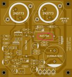
Per the schematic in post #1, pgnd goes to the main B+ filter cap minus, POS goes to the main filter cap +. I use a 3300 uf for two channels. The + of the main filter cap goes to the + of a 6 amp or bigger bridge rectifier (for two channels). The - of the main filter cap goes to the - of the bridge rectifier.So what should I connect to the PGND of this amp ? My transformer has only + and - wires. I also dont have protective earthing at my wall socket
Second thought I guess I won't find a good 2n3055. So I'll try with KD502. They are known for their durability and are very cheap (about 0,8$). Those Czechoslovakian transistor were very commonly used in power amps in Eastern Bloc countries. And lots of those amps still run very well. 20A, 60V,150W,2MHz is not bad I guess.
The AC outputs of the 36 v transformer go to the wiggle (AC) inputs of the bridge rectifier.
My 1970 build ST120 chassis with the AX6 in it has no connection to the safety ground of the wall socket. It is no longer legal to sell products like that. I don't have children or pets that touch the amp so I don't worry about it. The signal input ground is connected to the analog ground of the mixer that drives the amp through the ring of the RCA cable. There are various schemes to connect the analog ground to safety ground for chassis safety - one involves the AC terminals of bridge rectifier between analog ground and safety ground, parallel a capacitor, parallel a resistor. I'm not expert on doing that.
Genuine 2n3055 with much higher Ft (oscillation risk) are available from ST and ON semi, via authorized distributors like Farnell, Mouser, Digikey. I don't know names of authorized distributors in your country. Buying from physical stores or e-bay, the experience of your amp repairman friends helps you determine the likelyhood of getting genuine parts. Or you can test Iceo, use a 47 k resistor in series with the DVM ma scale.
Your KD number is famous enough, the counterfeiters may have jumped onto that number, too. The cost of a silk screen to mark counterfeit parts can be paid off with 10 parts. Real KD502 appear quite suitable to look at the datasheet.
I used NET60 output transistors, which were way expensive, but the only thing available in 1990 in a physical store in this small city before debit cards were popular. Newark (farnell) wouldn't sell to individuals those days.
NTE60 datasheet appears equivalent to MJ15003, a current production On semi number. I've gotten 24 VAC out of mine for whole seconds at a time into 8 ohms speaker (SP2-XT) using 70 v rail voltage. Using analog voltmeter to measure. My 2n5401 and VAS transistor gains may be exceptionally high, your results may vary.
Last edited:
36 v transformer gets you about 49 vdc rail if you use a bridge rectifier.
Into 8 ohms you might get 25 watts- from MJ15003 outputs like I have (NTE60) if the transformer will supply that much current.
KD502 or 2n3055 may current limit you, output transistor gain may starve above 1.5 amp. so 1.5 amp into 8 ohms would be 18 watts.
If you have MJ21194 outputs to 4 ohms speaker, if transformer will support the current, those will go ~4 amps at 50v, you could get 64 watts. of course the drivers have to produce some drive current. I've got TIP41c/42c as drivers, which limit the highest frequency a bit, but could theoretically put out 1 amp drive at soa limit, so my measured 24 vac into 8 ohms from 70 v rail seems quite theoretically possible. I was seeing 24 v needle swing on AC voltmeter on Rihanna Shut Up & Drive the heavy bass notes. Could be peaking more watts for very short transients like the cannon shots on 1812 overture, I just don't have equipment to measure 50 ms voltage peaks.
TO220 is fine to start experiment with. TIP41c/42c are $.38 each here from Fairchild, have about 1 amp soa. I use heat sinks on VAS, drivers too. Plus a fan.
Last edited:
If you can't make any run of the mill vintage or modern 100W audio outputs work safely on a single 50V supply, there's something seriously wrong. I've got a batch of fake 2SC3281's that would work fine. As well as many old TO3 pulls from God only knows where. Many old vintage receivers used TO220's. TIP33 or 35 would do - and could be made to fit. Where the requirements just aren't that demanding, you're way over thinking things.
Measure the voltage to ground on the bottom of the 0.47 Ohms, the side connected to the cap...it will probably be much less than 1/2 the rail voltage...if so the bottom power transistor might be turned on when it shouldn't, or shorted, of there might just be a solder bridge.
I have a 24-0-24 AC transformer. I connected The "0" to GND on the board and 24 to the "+" , then it gets very hot.(don't have time to measure the voltage cause I don't want to burn the resistor)
But when I only connect the positive wire and nothing to ground it doesn't get hot but I get only 0.20v on the resistor
But when I only connect the positive wire and nothing to ground it doesn't get hot but I get only 0.20v on the resistor
May I'm misinterpreting something...but are you putting AC or DC on the supply rail? It should be only DC.
DC of course, The 0 to GND and 35v DC to +
Apparently it connects the transformer without rectification and filtering!May I'm misinterpreting something...but are you putting AC or DC on the supply rail? It should be only DC.

- Home
- Amplifiers
- Solid State
- Retro Amp 50W Single Supply