I have a stupid question (sorry) : how many channels can be "teleported" (one-way) with this module?
4
Sorry, I was referring to data lines, not I2S channels, but coincidentally my answer is the same, as long as you do not need to supply master clock (MCK).
If you mean channels of I2S data, then you have:
Line 1: BCK
Line 2: LRCK
Line 3: DATA (2 audio channels)
Then another line for each 2 audio channels of I2S DATA.
Plus one line for MCK if needed.
Each Teleporter drives four lines, so for eight channels of I2S data, you need to run a pair of Teleport transmitters and a pair of receivers.
My old rack-mount DAC interface has been down for a while now. I was waiting for the USB interface but now with several non-TPA options available got more serious - only to realize that multichannel synchronization and/or DSP filtering on the XMOS chip are far from assured.
So I'm simply going to hack I2S from the ICE1724 chip of the old pci card right inside the PC and send it out using teleporters. I hope it is as easy as it sounds! A couple of questions: a) 5V from the computer PS OK to supply the 2 transmitting teleporters? b) any extra shielding recommended inside the PC chassis? The wires to the teleporter can be ~2" or less in length.
So I'm simply going to hack I2S from the ICE1724 chip of the old pci card right inside the PC and send it out using teleporters. I hope it is as easy as it sounds! A couple of questions: a) 5V from the computer PS OK to supply the 2 transmitting teleporters? b) any extra shielding recommended inside the PC chassis? The wires to the teleporter can be ~2" or less in length.
My old rack-mount DAC interface has been down for a while now. I was waiting for the USB interface but now with several non-TPA options available got more serious - only to realize that multichannel synchronization and/or DSP filtering on the XMOS chip are far from assured.
So I'm simply going to hack I2S from the ICE1724 chip of the old pci card right inside the PC and send it out using teleporters. I hope it is as easy as it sounds! A couple of questions: a) 5V from the computer PS OK to supply the 2 transmitting teleporters? b) any extra shielding recommended inside the PC chassis? The wires to the teleporter can be ~2" or less in length.
I did something similar with an Asus Xonar card. Worked well.
Powered Teleporters from PC PSU using standard molex connector.
(Have 4 Teleporters . 2 mounted on PC back plates and connected via ribbon cable to Xonar for sale, ready to go. If you are interested
") )
)
Last edited:
Thanks for that info. The convenient element of this (albeit old-school and short term) solution is that I don't have to change the ASIO setup nor the crossover filters/software. It should get me running with a SQ upgrade until better multichannel asynchronous methods are available. I already ordered new teleporters, though thanks for the offer…
Frank
Frank
Thanks for that info. The convenient element of this (albeit old-school and short term) solution is that I don't have to change the ASIO setup nor the crossover filters/software. It should get me running with a SQ upgrade until better multichannel asynchronous methods are available. I already ordered new teleporters, though thanks for the offer…
Frank
No Problem.
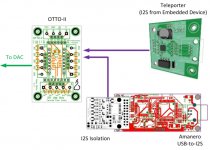
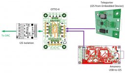
I'm setting my source up to be able to switch between a USB-to-I2S device (Amanero) and an embedded player (e.g. BBB). The latter will reside in a separate box with its I2S output "teleported" (TM ) to the D/A.
Parts are ordered and I'm now trying to choose between the attached layouts.
Will the Teleporter offer adequate isolation (Option A), or should I play it safe and isolate at the OTTO's output (Option B)?
) to the D/A. Parts are ordered and I'm now trying to choose between the attached layouts.
Will the Teleporter offer adequate isolation (Option A), or should I play it safe and isolate at the OTTO's output (Option B)?
Attachments
I'm setting my source up to be able to switch between a USB-to-I2S device (Amanero) and an embedded player (e.g. BBB). The latter will reside in a separate box with its I2S output "teleported" (TM
Parts are ordered and I'm now trying to choose between the attached layouts.
Will the Teleporter offer adequate isolation (Option A), or should I play it safe and isolate at the OTTO's output (Option B)?
I assume you have another Teleporter near the OTTO for receiving...
If you want isolation, it seems to make sense to use layout 2.
I assume you have another Teleporter near the OTTO for receiving...
Actually, the one pictured is supposed to be the receiving Teleporter.
All boards depicted in the graphs above are going to be part of the D/A box.
The BBB (or a similar device) will reside in a separate enclosure (with a transmitting Teleporter); not shown here.
I was just wondering if the LVDS transmission (with no grounds connected between the transmitting and receiving box, i.e. no shielded cable or anything) would offer enough of an isolation.
Yes! It indeed should give you all the isolation you need. If you find you need to connect the grounds (too much potential between them) then you can always add in the isolator, and if you do the right place would be after the OTTO and just prior to the DAC.
Just thinking out loud about a possible future project...
Assuming a high quality digital 'source' with i2s output as a starting point, I'm thinking about using two single channel (Left & Right) DACs but locating them, each in their own enclosure, away from the digital source.
Teleporter modules are the obvious way of achieving the remote connectivity. Each separate DAC would obviously require a Teleporter receiver but just wondering if I would need two transmitters at the source end, or could I use one transmitter and an RJ45 splitter, like this;
RJ45 CAT5e Cable Splitter UTP Network Data Economiser Ethernet DataData Adaptor | eBay
I believe a splitter will be fine but seeking confirmation.
Cheers
Ray
I don't know exactly how that splitter works, but at first glance I don't think that kind of splitter will work - because it looks like it works at a digital level...
Still what you want to do would be really simple, just stack two teleporter transmitters and use two teleporter receivers.
Also use shielded CAT5/6 for best results and connect the shield to GND at one end or both (up to you). There is a jumper close to the jack for connecting it to GND.
Cheers!
Russ
One transmitter and 2 receivers
What I would like to do is make a box using an Amanero USB interface input on one end, and a teleporter set to transmit on the other end. What I hope to accomplish is replace the need for a USB-AES/EBU conversion box to extract the audio out of my computer, and at the same time improve upon the quality of the signal transfer.
This box will send a signal to a pair of dsp plate amps that have a I2S input header. Currently the plate amps have a digital AES/EBU input, and a AES/EBU Through output so you can daisy chain them together with only 1 cable coming from the source. I would like to keep the setup exactly the same but use the teleporters instead.
Since the teleporter set to transmit sends 4 channels, would it be possible to just use 1 transmitter to send 2 channels to a teleporter receiver located on plate amp 1, and send the other 2 channels to a output RJ-45 receptacle located in plate amp 1?
From there another cable will send the other 2 channels to another teleporter located in plate amp 2. Would having the extra connections degrade the signal going to amp 2? Last thing I want is one channel to have better sound than the other.
Another question is, would I be able to order the teleporters as bare boards without the RJ-45 receptacles? My plate amps have Neutrik XLR inputs and output on them currently and if I could replace them with the Neutrik RJ-45 receptacles and connect them to the teleporter's it would be perfect.
Thanks in advance
You need all four channels to transmit I2S (BCK, LRCK, DATA, MCK (if used)).
That said, I have tested daisy-chaining the signals like this, but it may work. LVDS generally will be unhappy with dual-termination. A better solution would be to use one set between the source and first amp, then another set between the first amp and second amp.
Also, the RJ45 connector comes unsoldered for just this reason. It's easy to add, but tough to remove.
That said, I have tested daisy-chaining the signals like this, but it may work. LVDS generally will be unhappy with dual-termination. A better solution would be to use one set between the source and first amp, then another set between the first amp and second amp.
Also, the RJ45 connector comes unsoldered for just this reason
. It's easy to add, but tough to remove.
Last edited:
You need all four channels to transmit I2S (BCK, LRCK, DATA, MCK (if used)).
That said, I have tested daisy-chaining the signals like this, but it may work. LVDS generally will be unhappy with dual-termination. A better solution would be to use one set between the source and first amp, then another set between the first amp and second amp.
Also, the RJ45 connector comes unsoldered for just this reason
Sounds good. I'll just go the dual pair route. That will ensure both amps get the same quality of signal.
1 more thing, would increasing the quality of the power source used to power the teleporter in the transmitter box, be beneficial to the sound quality? I was thinking about using a 5.5v lithium battery power supply for it. It made a great improvement in sound with my Exasound DAC. I'm also going to use a high quality isolation board before the USB interface.
Do you have any other tips I could apply to make this device the best quality possible? Cost is no object, sound quality takes priority. My goal is to make a device that will exceed the sound quality of using a Berkeley Alpha USB with its AES/EBU outputs. Do you think this is possible?
Last edited:
- Home
- More Vendors...
- Twisted Pear
- Introducing the bit "Teleporter"