This company has put some clever options into their designs.
http://www.xkitzconnect.com/files/XOVER-2_Instr_Manual.pdf
Inputs and outputs can be either balanced or unbalanced.
Replaceable resistor boards to change the Xover frequency. Perhaps you could take this further and add switches to different resistor boards.
Also, THAT Corp has some nice IC for converting between balanced and unbalanced.
http://www.thatcorp.com/1200-series_High_CMRR_Balanced_Line_Receiver_ICs.shtml
Last edited:
That is what everybody else calls the specification phase: deciding what you want it to do.wfrohwein said:When i said design phase, i mean, i know what i want this eq to do, i know what filter cutoffs i want, i know what peaking / notch filters i want,
No. First you have to choose the filter architecture. Then you have to design the filters in a generic (e.g. frequency independent) sense. Then you have to calculate the C's and R's to get the frequencies and Q's you need (assuming cascaded 2-pole active CR filters - there are other options). Then you have to think about how you will do your switching to get click-free operation. Only then can you pick individual components.now just to pick the individual component and put it all together.
In the design stage you will answer questions. Some of those questions you may not yet be asking.
No. First you have to choose the filter architecture.
I chose 4th order buttherworth filters.
Then you have to design the filters in a generic (e.g. frequency independent) sense.
Then i did that in LTSPice
Then you have to calculate the C's and R's to get the frequencies and Q's you need
I did that using a formula i found for highpass and low pass filters.
I even started buying parts based on those numbers. I have a working breadboard with balanced inputs and outputs, a stereo set of 24hz 4th pole highpass filters. I have this all working with audio samples, then i started thinking about the amount of components it would take to build the complete unit, which is why i asked about decrease the amount of components.
thank you for your input, i appreciate any opportunity to learn more.
As I said, 4th order Butterworth is not a filter architecture. It is part of a filter specification. You possibly actually chose cascaded second-order Sallen-Key - but so far you have not told us.wfrohwein said:I chose 4th order buttherworth filters.
No, you simulated a design in LTSpice.Then i did that in LTSPice
The formula would have applied to a particular filter architecture. Another filter architecture implementing exactly the same 4th order Butterworth response would give different component values. So which filter architecture did you choose?I did that using a formula i found for highpass and low pass filters.
So which filter architecture did you choose?
I guess i did not choose one then. All i did was find a schematic for a 4th order butterworth filter, picked C and R values for the cutoff that i wanted, put it on the breadboard and made it work.
Here is the schematic i found.
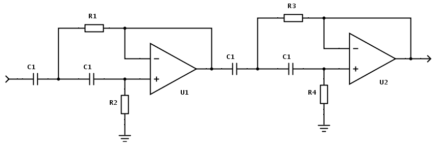
That is a cascaded 2-pole Sallen-Key filter. It can be used to generate Bessel, Butterworth and other responses - depends on the C and R values chosen. I note that the filename for that picture mentions Bessel.
Be aware that R2 and R4 provide bias for the opamp so if you switch them you need to ensure that bias is maintained, and it may be difficult to avoid clicks.
Be aware that R2 and R4 provide bias for the opamp so if you switch them you need to ensure that bias is maintained, and it may be difficult to avoid clicks.
Last edited:
it may be difficult to avoid clicks.
Thank you, i really appreciate the insight. Before this post i never through about swapping out resistors via a switch anyways. But it sounds like this design may not work well unless i do want to duplicate components. I have some rotary switches coming and i am going to try the design mentioned above and see if i like the way it sounds, so far that sounds like the only option.
I really wanted to see how dangerous does their bax eq. I asked for schematics but they said no. I guess its taboo to ask for this kind of thing, even though one of the biggest manufactures sent me a schematic for free with very little questions asked.
Much to learn. Thank you again and i got some homework and testing to do.
That is using Unity Gain S&K filters.I guess i did not choose one then. All i did was find a schematic for a 4th order butterworth filter, picked C and R values for the cutoff that i wanted, put it on the breadboard and made it work.
Here is the schematic i found.
If you decide to keep fixed matched capacitors (you need 4 per stage and you have omitted some of them) then you find that the resistors will end up being 4 different somewhat odd values. Now making them switchable using UG S&K becomes a real chore.
In my view you would find this much easier if you chose the ECV S&K.
Last edited:
In my view you would find this much easier if you chose the ECV S&K.
Did you just read my mind? I was just thinking, how am i gonna use this filter design and switch out those resistors in a quiet non clicking manner. So i am definitely going to research the method you spoke of and do some bench tests and see how i like the sound.
I think any filter will click if you switch resistors while it is live.
You may find that adding in a parallel resistor via a switched make before break is quiet during the switch over. Worth trying a few experiments.
The ECV S&K filter is detailed in all of those Ti docs
BTW,
you don't need a switched, you can use a swap arrangement.
Build up an 8pin or a 14pin DIP header with the resistors you want for a particular frequency and swap it into a DIP socket.
It depends on whether you need a live type frequency change.
Last edited:
oh thats awesome. I will definitely look into this. I only chose the buttherworth because of flatter frequency response at the passband. I am designing a mastering grade eq so i wanted things to be as transparent as possible. Thank you for your input.
If you are not tied to using a butterworth filter then you could use a fourth order Linkwitz-Riley which is made of two identical second order butterworths cascaded, so all the components could be of equal value.
I have a question about opamps if you dont mind. I am currently using INA137's and DRV134's to handle my input and output of balanced audio. Should these be discrete opamps as well?
I have a schematic from a very popular mastering eq and they use a dc servo input to handle the balanced audio firstly going through an OPA2604 and a pair of MJE3055/MJE2955. So i am curious, if i went with discrete opamps for all my filters, would it be a waste to go through the ina137/drv134's ?
No matter how the preceeding and successive stage is buildt, an improvement is never lost. So it will still be worth it to choose, say discrete circuitry in one stage and an opamp/IC in another stage if you feel that this is exactly how it should be.
The discussion of opamps/ICs versus discrete in general is a matter of taste. I could give you my recommendations, but there will be others who would recommend other solutions.
I personally use a mix of discrete and opamps. I would love to have everything discrete, because I think it sounds better, but it is sooo much easier with opamps. And my active filter is constantly changing, because my speakers are constantly changing.
Anyway I recognize the need for absolute precision when it comes to balanced driving, so the optimum solution could very well be opamps in the balanced in/output and discrete circuitry for the filters.
Personally I think the sound of the OPA2604 is to 'dry', I prefer the OPA2134 witch has a good balance of details and warmth. (This is pure subjectivism, I know)
Regarding the 'click' when using switches: it is no big deal. You will already know that you are switching frequncy anyway, and you will only perform that operation a few times, and then you will leave it in a fixed position.
The hard part is probably to find 4-position switches with 8 or even just 4 poles. You could also choose to switch frequency with PCB DIP-switches. Many others do that as well.
I can read that you are already in a steep learning curve, so I would hate to 'confuse' you even more. But I must recommend this video of Douglas Self explaining a lot about active filtering. Even if I already felt like I knew everything there was to know about active filters, I did learn quite a few things. His tips and tricks regarding capacitor types and his noise considerations are really good things to be aware of.
If you are not tied to using a butterworth filter then you could use a fourth order Linkwitz-Riley which is made of two identical second order butterworths cascaded, so all the components could be of equal value.
I will definitely looking into that. Being able to share a good amount of components would definitely save some build cost. I just need to figure out where i want to draw the line. If i built it like i initially intentioned, this thing would cost over $8000 to build, who would buy that lol
Thank you for your input. It is much appreciated.
you are already in a steep learning curve
No kidding, but it is fun for sure. It definitely seems dooable once i get around all the lingo. Having some circuit experience and being a dull time software developer i feel helps me in my journey as i naturally have a technical problem solving type of mindset.
You are right about possibly building a hybrid system with opamps / discrete. I built the 2520 opamp from capi and it sounds amazing. I also just ordered a pair from Hairball Audio and plan to order a pair of Supreme Sound Opamp V5 from Burson Audio. I want to hear with my own ears how they sound.
As for the click, im sure its something that i might be able to get past. If the prototype turns out well, i have some mastering engineer friends i wanted to send it to, and i just wanted to make sure i am sending something that is a good as possible.
Thank you for your input. Overall everyones input from this thread has been great. I am learning a ton and having a ball doing it.
I don't remember you mentioning before in this thread that this might be for sale. Maybe you were joking?wfrohwein said:If i built it like i initially intentioned, this thing would cost over $8000 to build, who would buy that lol
I don't remember you mentioning before in this thread that this might be for sale. Maybe you were joking?
Well my plan is to have something that works to send to some buddies to see how they like it as well. If if they do, maybe start making them for sale. I know what would make my life easier in the studio, maybe someone else would benefit from it.
If you do manage to sell any perhaps some of the profit could be donated to this forum, in recognition of the free training and consultancy you have received here? You may need input from people who know how to make a safe legal power supply, and satisfy EMC regulations etc. For example, in many jurisdictions it is now a requirement that mains power supplies have good power factor.
- Status
- This old topic is closed. If you want to reopen this topic, contact a moderator using the "Report Post" button.
- Home
- Source & Line
- Analog Line Level
- Multiple Butterworth filter question