Hi shaan , does not know much about measurements but mr linkwitz publishes different method and advocates IM distortion - "Harmonic distortion products are below 0.01% for the three amplifiers measured. But musical signals are rarely single sinusoids. Intermodulation distortions are always higher than harmonic distortions and their spectral distribution is in my opinion a better differentiator between amplifiers than a single harmonic distortion number"
This is his Quote from one of his page and obviously i donot understand fully but he measures with mixed 1khz and 5. 5 kHz sine wave fluctuating at 4.5 khz at 1w and 500mw levels in to 8 ohm load, and last amplifier he has measured was ncore module (class d by burno putzeys)based from ATI and he has said the best amplifier he has measured till date
Do know merits of it but mr linkwitz is whiz
If possible measure IM distortion too
Below is the link to the page iam referring ,forgive any stupidity
LX521 Supplies
Hello drgnanam!
 Glad to see you again! How do you do? How is DIY going?
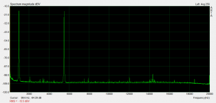
I was going to do more THD tests but after checking the link I totally lost track of what I was supposed to do before and ended up taking an IMD spectrum of V4 with 1KHz+5.5KHz at 1.7WRMS into 8ohm. Tell me how it looks. (I hope not too bad)
")
Attachments
Hi shaan, i just know that linkwitz recommends IMD rather than 1k distortionand 1watt and below distortion rather than full power distortion as distortion is heard more during quite passage music than during loud passge of music,its is sync with mr pass who says first watt is more important
Other than that i do not much about measuring and interpartation ,that where intelligent guys like u i decent
My diy is stuck at cabinet stage , i am doing cabinet now
Will update once it finished it . cabinet is more difficult than amplifier itself that much i can say and iam waiting for v2 of v4
Other than that i do not much about measuring and interpartation ,that where intelligent guys like u i decent
My diy is stuck at cabinet stage , i am doing cabinet now
Will update once it finished it . cabinet is more difficult than amplifier itself that much i can say and iam waiting for v2 of v4
Hello drgnanam!
I was going to do more THD tests but after checking the link I totally lost track of what I was supposed to do before and ended up taking an IMD spectrum of V4 with 1KHz+5.5KHz at 1.7WRMS into 8ohm. Tell me how it looks. (I hope not too bad)
you could run the exact same test against v3 and compare.
Thanks for the test.
Hi shaan, i just know that linkwitz recommends IMD rather than 1k distortionand 1watt and below distortion rather than full power distortion as distortion is heard more during quite passage music than during loud passge of music,its is sync with mr pass who says first watt is more important
Other than that i do not much about measuring and interpartation ,that where intelligent guys like u i decent
Very interesting. Thank you for sharing the information. I wish I was half as intelligent as these two men, though.
My diy is stuck at cabinet stage , i am doing cabinet now
Will update once it finished it . cabinet is more difficult than amplifier itself that much i can say and iam waiting for v2 of v4
Wish you a fast build.

you could run the exact same test against v3 and compare.
Thanks for the test.
You're welcome but right now my table is full of stuffs and replacing the amplifier is a hassle. But don't worry I will do that as soon as V4 tests are done. I am curious too as I haven't done IMD tests on any previous PeeCeeBee.
IMD is inversely proportional to slew rate, and V4 has higher slew rate than the last versions. So V3 IMD may be higher than V4. We will see.
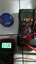
I tried to install 22k and lowest bias was around 140 mV, now I put 2k2 in series to 22K then I can set bias from 90 mV to 120 mV approximately. I set 113 mV heatsinks were a little bit warmer now, dc offset for both channels are 0,1 – 0,3 mV.
Is it possible to install 22k + 5k timmer potensio (VR) instad of 22k + 2k2 + 2k2 (5k timmer potensio (VR))?
Thank you. Best Regards
Is it possible to install 22k + 5k timmer potensio (VR) instad of 22k + 2k2 + 2k2 (5k timmer potensio (VR))?
Thank you. Best Regards
Attachments
Is it possible to install 22k + 5k timmer potensio (VR) instad of 22k + 2k2 + 2k2 (5k timmer potensio (VR))?
Yes it is.
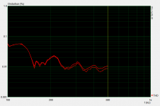
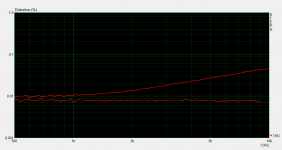
Here is a couple THD vs Frequency traces of V4 at 17VRMS into 8R load (~40W). First shows 100hz to 500hz and the second shows from 500hz to 10khz. In both pictures the lower trace shows source THD and upper trace shows amplifier THD.
The source (PC onboard soundcard) is a horrible generator in low frequency and not too good either at high frequency but behaves a bit better above 200-300Hz. This is why in my last tests I used an external signal generator with a steep low pass filter that gave me 0.002% source distortion, but for this test one must use ARTA STEPS's internal generator. No way around this and I don't own an AP SYS-2702.
Comparing the traces we can still figure out the amplifier's distortion. As shown, low frequency THD below 200hz is around 0.0005%.
However, THD gradually increases with frequency and as measured at 10khz it is 0.033%! V4 uses only dominant pole compensation but this figure is higher than expected thanks to the BD139/140.
Using MJE or 2S pairs is almost a necessity here, especially if THD below 0.01% at 10khz is to be expected. (for me it doesn't matter as I can't hear anything above 16khz and V4 sounds crystal clear with every HF material I threw at it, with the BD pair)
Anyways, my experiment with V4 was to try to lower its LF distortion way below previous peeceebees' typical 0.01% that I used to measure. Now its wayyy below.
p.s. the layout has been finalized with resistor trimming of MOSFET bias. that's all that changed from the prototypes, two diodes removed, one trimmer added. the GB will start soon. keep an eye on the index.
Attachments
Here is a couple THD vs Frequency traces of V4 at 17VRMS into 8R load (~40W). First shows 100hz to 500hz and the second shows from 500hz to 10khz. In both pictures the lower trace shows source THD and upper trace shows amplifier THD.
The source (PC onboard soundcard) is a horrible generator in low frequency and not too good either at high frequency but behaves a bit better above 200-300Hz. This is why in my last tests I used an external signal generator with a steep low pass filter that gave me 0.002% source distortion, but for this test one must use ARTA STEPS's internal generator. No way around this and I don't own an AP SYS-2702.
Comparing the traces we can still figure out the amplifier's distortion. As shown, low frequency THD below 200hz is around 0.0005%.
However, THD gradually increases with frequency and as measured at 10khz it is 0.033%! V4 uses only dominant pole compensation but this figure is higher than expected thanks to the BD139/140.
Using MJE or 2S pairs is almost a necessity here, especially if THD below 0.01% at 10khz is to be expected. (for me it doesn't matter as I can't hear anything above 16khz and V4 sounds crystal clear with every HF material I threw at it, with the BD pair)
Anyways, my experiment with V4 was to try to lower its LF distortion way below previous peeceebees' typical 0.01% that I used to measure. Now its wayyy below.
p.s. the layout has been finalized with resistor trimming of MOSFET bias. that's all that changed from the prototypes, two diodes removed, one trimmer added. the GB will start soon. keep an eye on the index.
Thanks for the measurements.
Beginner question : V3 has this same behavior on HF? why you so concerned about lower frequency THD , isn't HF thd much more audible? specially from 1k to 7k?
Thanks for the measurements.
Beginner question : V3 has this same behavior on HF? why you so concerned about lower frequency THD , isn't HF thd much more audible? specially from 1k to 7k?
With the same transistors that I am using now in V4, V3's performance will be worse at HF.
It's actually the order of harmonics that matters when we are talking about audibility with real-world signals. And for any fundamental frequency, any harmonic beyond 5th is more audible at the same magnitude as the second, third or fourth. The 7th harmonic is especially audible even at a lower magnitude than all previous harmonics. But in V4 the higher measured THD for 5-7khz sinewave is composed almost entirely of second and third harmonics and almost everything beyond 4th is close to noise floor. Safe.
Sonic perception is very private, still I will try to express it as much as I can. I feel LF distortion makes the bass notes kind of disconnected from the rest of the music, i.e. tone variations in the lowest octaves sometimes feels out-of-place. In many listening tests I was a bit puzzled by this while there are many who thought the bass is just fine. Lowering the LF THD of the "next" peeceebee was a personal quest for me and I am very happy that V4 does exactly that without hurting the other octaves and the sonics of it says it all.
After the V4 is released I would love to see a version with 2 pairs mosfets that could run on +-60V...
+1
After the V4 is released I would love to see a version with 2 pairs mosfets that could run on +-60V...
Sure. But do you mean V4 is neither a winner nor a keeper?!
Never mind I get you.

???? What is this?????
This is SPARTAAAAAAAAAAAAAAAAAAA! ok just kidding
____________________________________________________
Update: The V4 GB thread will be launched tomorrow. All invited to join the fun. GB link will be shared here as soon as thread is online.
- Home
- Amplifiers
- Solid State
- PeeCeeBee