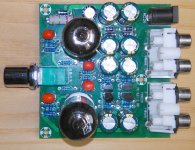
I have 2 pieces of this cheap tube preamp/buffer :
foxein FE-6J1-2.0B
Tube preamp kit FE-6J1-2.0B |
Both of them are useless from the very beginning, they produce the same distorted sound. I have attached a simple recording (mp3/zip) of the issue. I was wondering if anyone could point a failed part in the circuit by hearing the sound.
Tubes are all ok, tested.
thanks
Attachments
Last edited:
What sort of power supply do you use? It must be a transformer (AC/AC) type, 12VAC output nominal (ideally ~12.6 VAC loaded) @ about an amp.
What kind of voltages do you get on the tube pins with respect to ground? Not sure which of these electrolytics should have the +/-28 V supplies on them.
What kind of voltages do you get on the tube pins with respect to ground? Not sure which of these electrolytics should have the +/-28 V supplies on them.
thanks for the reply, I have used 2-3 different 12V power supplies, same result, one of them is a relatively high quality 3A from a hard disk drive. This is the one I use in an other working flawlessly tube buffer but with different design. All tubes tested there also as it is of the same type 6j1.
Tubes also seem to warm up correctly in both circuits, it seems that the fail is the same on both.
I have a multimeter, but not sure what to do because I do not have the knowledge to do it, but I can follow instructions. Because the units are very cheap and safe to test I would do it if someone will have the patience to describe it simply... thanks again
Supplies used for harddrives tend to be DC output though, since you need a +12V DC supply anyway (as long as we're talking 3.5" drives, which are running their spindle motor driver from this). This circuit absolutely needs AC voltage (V~, not V=), i.e. a "dumb transformer" with nothing else. This is important. Please post the output specs printed on the supplies you have.thanks for the reply, I have used 2-3 different 12V power supplies, same result, one of them is a relatively high quality 3A from a hard disk drive.
When mistakenly supplied with 12 V DC, the heaters would in fact work correctly (depending on polarity), the rest not at all.Tubes also seem to warm up correctly in both circuits, it seems that the fail is the same on both.
OK, go to Youtube and type in "multimeter tutorial". Once you have a decent clue how to measure voltages and resistance and check for continuity (assuming your multimeter has a continuity test mode that conveniently beeps, otherwise staring at the display in resistance mode it is), proceed with the next step.I have a multimeter, but not sure what to do because I do not have the knowledge to do it, but I can follow instructions.
Next, find a convenient ground point on the board. Check continuity between RCA jack outer shell and jack connections, then follow the trace by eye until it arrives at some spot that's convenient for putting a multimeter probe on, and verify continuity. That's where the black probe will go and stay for now.
Set multimeter for voltage mode, maybe the 20 VDC range for a star if it's not autoranging.
Note that tubes are generally displayed in bottom view, with numbering running clockwise. So you can just start at the gap, put your probe on the first pin, read multimeter, note down voltage, and proceed to the next one.
If you can see where pin 5 goes, you might spot the 4.7 kOhm plate (anode) resistor right away, otherwise consult resistance mode. Likewise, pin 7 should go to the 200 ohm cathode resistor. If you have identified these two, go back to voltage measurement mode and determine the voltages on both ends of these resistors with respect to ground.
Last edited:
hm..., you made a good first point here, I have not noticed the AC mark on the board, and this is because I use an other device that is designed to work with DC power supplies (Feixiang FX-AUDIO TUBE-01 DC12V) ...
So I will have to check if I have an AC power supply or find one.. and start from there.
Thanks!
So I will have to check if I have an AC power supply or find one.. and start from there.
Thanks!
Last edited:
Unfortunately, since both units perform the same, you probably are getting the performance that design is intended to deliver. In other words, it's probably a failed design rather than failed parts. Or, perhaps, it is a successful design as a distortion generator. Which may actually have been the design objective.
I'm not familiar with the 5654 pentode (which appears to be triode strapped), however, two design aspects jump out at me as being suspect. The first is the plate load of 4.7k, which seems low. Generally speaking, the lower the plate load, the greater the distortion that's produced. The second is the relatively low supply voltage of 56V. Taken together, these are probably a recipe for high distortion. I don't know that there's an easy fix, aside from dropping them in your waste basket.
I'm not familiar with the 5654 pentode (which appears to be triode strapped), however, two design aspects jump out at me as being suspect. The first is the plate load of 4.7k, which seems low. Generally speaking, the lower the plate load, the greater the distortion that's produced. The second is the relatively low supply voltage of 56V. Taken together, these are probably a recipe for high distortion. I don't know that there's an easy fix, aside from dropping them in your waste basket.
Premade AC/AC wall-warts are a bit exotic, yeah. You might find an old one from the world of telephony, or you may be able to convert a (transformer-based, read: heavy) ~15 VDC supply. (You literally just need a transformer in a case.) Other than that you are probably best off looking at the usual electronics part distributors. If all fails you may have to build a power supply yourself around a bare 230V~/12V~ transformer of 12-15 VA (preferably in a plastic case for obvious reasons).I have checked more than 10 power supplies and they are all DC, I guess the devices I currently use are all DC, maybe is a bit rare to have an AC input device, I do not know
If you have a spare (hi-fi) speaker power amp (at least a real 20 W / 8 ohms or 40 W / 4 ohms conservatively rated, preferably not bridged, so internal supplies should be about +/- 20 V minimum), you could try feeding a 50 Hz sine wave into that one and adjusting levels until you get the desired 12.6 VAC output according to your multimeter, then solder some wires to the AC input terminals on the preamp board for connection. It's not exactly the most efficient way of building a power supply but should do for testing.
Last edited:
I have just seen some descriptions on different sites like ebay for this device. Some of them note that you cannot use DC power supply. One of them has the following note written with a Chinese to English odd translation, about some kind of psu modification, so here it is:
http://www.ebay.com/itm/6J1-Tube-Pr...6J1-2-0B-w-Case-AC-12V-1A-CH2-0-/201741916006
Feature:
Package including:
http://www.ebay.com/itm/6J1-Tube-Pr...6J1-2-0B-w-Case-AC-12V-1A-CH2-0-/201741916006
Feature:
- Model: FE-6J1-2.0B
- Channel Type: 2.0 / Stereo
- Power input: AC12V 1A /5.5 * 2.5 plug
- Knob function: power switch / volume adjustment
- Weight: 82g
- Machine size: 77*75*52mm
- Recommended power supply: AC12V 1000mA (The power supply is retrofitted with an output of AC 12V. How to retrofit? Open the power adapter housing, and then remove the rectifier filter circuit board, directly weld the output wire to the transformer output wiring head.)
- This is a 12V AC output power adapter, the label is written DC12V1000mA, but the internal circuit after processing, so that the output becomes AC12V1000mA, specifically for FE-6J1-2.0B.
- AC 12V input: DC5.5 * 2.1 socket, AC 12V power adapter can be used, you can also use the AC 12V transformer, if you want to use AC 12V transformer, you need to wire the power cord soldered on the circuit board. Note: Do not use the DC power input, otherwise it does not work!
- Left channel input / Right channel input: Audio signal input, can be connected to the phone, computer, M3, MP4, and other music players.
- Left channel output / Right channel output: Audio signal output, can be connected to the audio signal input of amplifier, amplifier board.
- Power switch / volume knob:
- Turn the knob counter-clockwise to begin lowering the volume. The power turns off and the indicator goes out., if you continue to rotate until the "click" is heard.
- In the off state, turn the knob clockwise, hear "click", the indicator light, indicating that the power has been turned on, then the volume is the smallest, and then continue to clockwise rotation is to increase the volume.
- An externally hosted image should be here but it was not working when we last tested it.
Package including:
- 1pcs 6J1 Tube Preamp Board Stereo Amplifier
- 1pcs Case without Rear Baffle
Last edited:
To clear things a bit, those sellers claim that someone can moddify a 1A DC psu to AC output (Without pointing a specific one) by removing a part of their internal components: remove the rectifier filter circuit board and then directly weld the output wire to the transformer output wiring head.
Can someone confirm this and point what kind of psu can be modified? Is this possible?
Can someone confirm this and point what kind of psu can be modified? Is this possible?
This is exactly what I was suggesting earlier, though they obviously mean soldering (finest Chinglish at work) and the 12 V supply should be closer to 15 V= if unregulated... though I have a nominal 12 V / 1000 mA DC supply from an old Taiwanese DSL router that measures over 15 V= unloaded, that would be quite suitable for example. (Vdc,out ~= Vac * 1.414 - 2 * Vdrop,diode for a bridge rectifier, so for 12 V~ in and about 0.7 V per diode drop we get ~15.5 V= out. You'd ideally want something with ~16.4 V=.) These tend to be ultrasonically welded even when screws are present though and require some effort in opening (I've seen one guy hammering in a sharp knife blade when opening a laptop power supply, that struck me as more elegant than some other methods).
This method obviously works for transformer-based supplies only, but these are easy to tell as a 12 V 1 A job is quite chunky and heavy already, far more so than an equivalent switching supply.
This method obviously works for transformer-based supplies only, but these are easy to tell as a 12 V 1 A job is quite chunky and heavy already, far more so than an equivalent switching supply.
Last edited:
@pentajazz,
were you able to test the unit with AC power supply ?
Unfortunately not yet, i might have to pass this mod to a professional as I am not sure if I can do it right.
Unfortunately not yet, i might have to pass this mod to a professional as I am not sure if I can do it right.
ok,,Hope it works out well
Unfortunately not yet, i might have to pass this mod to a professional as I am not sure if I can do it right.
The unit needs an AC power since it will be converted to DC via multiplier to get higher B+ for the tubes so that it will sound good. 6J1 needs 120v DC plate voltage. This might be similar to the schematics of 6N3 tube with voltage multiplier.
Just use 12v AC and your problem might be solved.
This must be the schematics of it:
http://www.epanorama.net/newepa/wp-content/uploads/2016/08/tubepre.png
Last edited:
- Status
- This old topic is closed. If you want to reopen this topic, contact a moderator using the "Report Post" button.
- Home
- Source & Line
- Analog Line Level
- tube preamp buffer with distorted sound