Here are the result of an experiment:
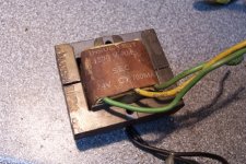
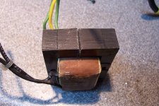
I have gapped the magnetic circuit of a power transformer by cutting two saw grooves in each outer leg.
This resulted in a gap of ~1.25mm average.
The transformer was a 117V to 24V CT, 16VA.
With the cuts, the primary inductance is 650mH, for 39Ω resistance, and the secondary 30.8mH for 3.2Ω.
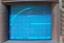
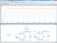
The oscillogram shows the current vs. V*s behavior of the secondary under power conditions: vertical scale 1A/div, horizontal scale 50V.ms
Even at 3.5A, there is no sign of saturation. The exponential look of the waveform is caused by the 3.2Ω of copper.
Such an inductor could be used in relatively low voltage supplies, whereas the primary could be used in tube circuits
The inductor thus created is far from optimal, because only half of the copper is used, and we can deduce from the waveform that the groove is too wide to be optimal, but it is nevertheless an useful choke.
I have a number of 117V/60Hz transformers that I have no use for (I live in a 230V/50Hz area), and they could be recycled usefully in that way
I have gapped the magnetic circuit of a power transformer by cutting two saw grooves in each outer leg.
This resulted in a gap of ~1.25mm average.
The transformer was a 117V to 24V CT, 16VA.
With the cuts, the primary inductance is 650mH, for 39Ω resistance, and the secondary 30.8mH for 3.2Ω.
The oscillogram shows the current vs. V*s behavior of the secondary under power conditions: vertical scale 1A/div, horizontal scale 50V.ms
Even at 3.5A, there is no sign of saturation. The exponential look of the waveform is caused by the 3.2Ω of copper.
Such an inductor could be used in relatively low voltage supplies, whereas the primary could be used in tube circuits
The inductor thus created is far from optimal, because only half of the copper is used, and we can deduce from the waveform that the groove is too wide to be optimal, but it is nevertheless an useful choke.
I have a number of 117V/60Hz transformers that I have no use for (I live in a 230V/50Hz area), and they could be recycled usefully in that way
Attachments
Last edited:
With a bit of cleverness, the problem of copper under-utilization can be fixed:
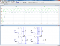
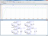
The two first pics show the low voltage and high voltage chokes, with the improvement they bring about compared with plain capacitance.
In both cases, the improvement is already substantial despite the modest values of the filter components.
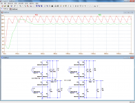
But we can go further, and use them both at the same time by applying a "synchronous filtering" scheme: in the next two pics, the inductors are now coupled, as they are in reality.
Not only is the copper fully utilized now, but the filtering quality is improved for both outputs!
Of course, this demands a little bit of care, like matching the ratio and the capacitances, and it is only usable where the current draw on both outputs is stable or vary in the same way, but it could be usable in SE class A amp for example: the low voltage for DC heating, and the high voltage for the anode voltage
The two first pics show the low voltage and high voltage chokes, with the improvement they bring about compared with plain capacitance.
In both cases, the improvement is already substantial despite the modest values of the filter components.
But we can go further, and use them both at the same time by applying a "synchronous filtering" scheme: in the next two pics, the inductors are now coupled, as they are in reality.
Not only is the copper fully utilized now, but the filtering quality is improved for both outputs!
Of course, this demands a little bit of care, like matching the ratio and the capacitances, and it is only usable where the current draw on both outputs is stable or vary in the same way, but it could be usable in SE class A amp for example: the low voltage for DC heating, and the high voltage for the anode voltage
Attachments
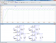
Another way of putting the free winding to good use is to tune it to the ripple frequency.
It would seem to be disadvantageous compared to the direct tuning of the active winding: the losses are doubled and the Q is therefore halved.
However, there are a number of benefits: the capacitor can be much smaller, meaning a stable, Hi-Q plastic type is usable, and the additional impedance introduced by the windings resistance and the leakage inductance avoid the direct coupling of HF crud to the output.
The improvement is nevertheless sizable:
Attachments
Even at 3.5A, there is no sign of saturation.
Is it safe running it at 3.5A continuously as i noticed that your secondary is rated at 700mA. How does one determine a transformer's amp rating actually? Is it simply from the enameled wire diameter? I'm curious as i have a spare 1A transformer that i can experiment with. I need a choke for a class A idling at 3-4 A.
No it isn't, but the curve tracer operates at a very low duty cycle, this allows to investigate well beyond the "normal" current of a component.Is it safe running it at 3.5A continuously as i noticed that your secondary is rated at 700mA .
In this case, it shows that it remains perfectly linear, even under severe overload condition. This means that it would be suitable even for "noble" jobs, like in a crossover filter.
There are many methods, approximations and rules of thumbs. Some have already been discussed here:How does one determine a transformer's amp rating actually? Is it simply from the enameled wire diameter? I'm curious as i have a spare 1A transformer that i can experiment with. I need a choke for a class A idling at 3-4 A
http://www.diyaudio.com/forums/power-supplies/240849-how-know-transformer-power-rating.html
http://www.diyaudio.com/forums/powe...ansformer-ratings-cross-sectional-area-2.html
http://www.diyaudio.com/forums/power-supplies/156030-trafo-unknown-power-rating.html
In the case of a multiwinding transformer, you can use this method:
http://www.diyaudio.com/forums/powe...r-each-winding-multi-winding-transformer.html
From one of your links:
In the case of gapped transformer, does the above still apply? With the core no longer saturates, my logic would conclude that the amp rating is now only determined by the wire gauge.. am i wrong?
The core power handling capability is a function of the product of the core cross sectional area and the winding area.
In the case of gapped transformer, does the above still apply? With the core no longer saturates, my logic would conclude that the amp rating is now only determined by the wire gauge.. am i wrong?
If you gap a transformer, it means that you no longer intend to use it as a transformer (OK, could be a flyback Xformer, but that would be far-fetched).
In which case, the power rating is meaningless.
The current rating still applies, and it could be determined by the wire gauge or the core capacity, but with this method of gapping, the copper limit will be exceeded well before the iron limit
In which case, the power rating is meaningless.
The current rating still applies, and it could be determined by the wire gauge or the core capacity, but with this method of gapping, the copper limit will be exceeded well before the iron limit
A 1A winding will withstand 4A (peak) only if the rms current does not exceed 1AThanks! Looks like i'm gonna bite the bullet and try gapping my 1A transformer as a 4A choke.
Just want to share my findings. I don't feel right ruining a perfectly working 1A transformer so i went to buy a roll of 0.8mm enameled wire. Seller have them by the weight, so i bought about 200 gr and have him roll it. The winding is nowhere neat and tidy as you can see below.
Replaced my 0.5R/10W resistor with this inductor (CRC now CLC) and suddenly my amp is now very quiet. Voltage drop is about 3 times higher than the resistor, meaning that the DC resistance must be higher. I have no low-ohm meter so i can't measure. Don't even ask me what the resulting inductance value is. All i know is that it works, albeit very hot. Can't touch my finger on it for more than 2-3 seconds.
Now i wonder, did my hum vanished because of the inductance or simply because the increased DC resistance compared to the resistor?
An externally hosted image should be here but it was not working when we last tested it.
Replaced my 0.5R/10W resistor with this inductor (CRC now CLC) and suddenly my amp is now very quiet. Voltage drop is about 3 times higher than the resistor, meaning that the DC resistance must be higher. I have no low-ohm meter so i can't measure. Don't even ask me what the resulting inductance value is. All i know is that it works, albeit very hot. Can't touch my finger on it for more than 2-3 seconds.
Now i wonder, did my hum vanished because of the inductance or simply because the increased DC resistance compared to the resistor?
Now i wonder, did my hum vanished because of the inductance or simply because the increased DC resistance compared to the resistor?
Such an air-core inductor will probably have little influence on the raw ripple amplitude. A three fold increase in resistance will reduce the ripple in the same proportion, but the inductance will have a more subtle effect, although the improvement on the 100Hz or 120Hz is probably not significant: it will affect the many harmonics present in the ripple waveform and remove most of its harshness and unpleasantness: you can tolerate a relatively high level of 100Hz if it is a clean sinewave.
it isn't half bad idea cutting a slot in the core of an old transformer like that.. heck, i've got a drawer full of relatively useless transformers..
as far as the optimum gap to use.. well that's entirely relative.
not so well understood is the 4/3rds power law that governs electro-mechanical machines, so for 10-200 watt transformers, you can probably estimate that relatively low losses will be achieved at the highest practical energy storage using the stock 1/2 winding which fills say, 30% of the core, the gap would need to be on the order of one thousandth the iron core length.
which is like, .2mm
leakage flux would cut that in half.
so if you've got a .025" slitting saw and a milling machine.. that's what i'd use.
or just go for the smallest gap you can cut and find a bigger transformer.
I think you can also use those sub-woofer crossover filters for chokes, like this one.
Just make sure you increase the capacitor values by A LOT. Basically you just use the inductors. They come with iron-core and typically valued at 5-10mH. 5mH with 10,000uF will yield 22 Hz low pass which i think should be good enough to remove those 100-120Hz hum.
I'm getting a cheap one tonight for 5 USD and will test it on my amp. I'm hoping for less DC resistance.
Last edited:
Elvee, interesting idea there!
Now I'm regretting all the old transformers I've thrown away over the years. I've been collecting model numbers of gapped power inductors (for use in a choke-fed SS SE class-A amp I made, there's a thread at http://www.diyaudio.com/forums/solid-state/303675-2nd-spring-another-stab-se-choke-fed-class-power-amp.html). Purpose made inductors can get expensive (though not when compared to SE transformers that SET tube amps would use) -- but this could be a great way to use surplus power transformers. Thanks!
Now I'm regretting all the old transformers I've thrown away over the years.
I've been collecting model numbers of gapped power inductors (for use in a choke-fed SS SE class-A amp I made, there's a thread at http://www.diyaudio.com/forums/solid-state/303675-2nd-spring-another-stab-se-choke-fed-class-power-amp.html). Purpose made inductors can get expensive (though not when compared to SE transformers that SET tube amps would use) -- but this could be a great way to use surplus power transformers. Thanks!I wonder whether something like these rotary cutoff disks might be a better way than using a bandsaw or hacksaw (I don't know how thin the disks are, though. It might be worth my taking a trip to Harbor Freight to find out?)
Diamond Rotary Cutting Discs 5 Pc
6 Piece HSS Saw Blade with Mandrel Set
Diamond Rotary Cutting Discs 5 Pc
6 Piece HSS Saw Blade with Mandrel Set
- Status
- This old topic is closed. If you want to reopen this topic, contact a moderator using the "Report Post" button.
- Home
- Amplifiers
- Power Supplies
- Gapped power transformer as a choke