Wesayso: I think I was unclear because I confused a few folks with my comment. I'm not interested in pursuing shading, that is, varying drive to the different panels. I meant to bring up the possibility of gradually tapering the high frequency output of each panel by putting some thin felt over the top and bottom cm or two. Sort of like RAAL's ribbon (see attachment).
The difference is that I wouldn't be trying to broaden the directivity vertically. I'd be interested in seeing what it does to the sharp ripples that show up where there are gaps between my panels. Of course what I want it to do and what it actually would do may not overlap.
Sorry for the confusion.
Few
Attachments
Wesayso: I think I was unclear because I confused a few folks with my comment. I'm not interested in pursuing shading, that is, varying drive to the different panels. I meant to bring up the possibility of gradually tapering the high frequency output of each panel by putting some thin felt over the top and bottom cm or two. Sort of like RAAL's ribbon (see attachment).
The difference is that I wouldn't be trying to broaden the directivity vertically. I'd be interested in seeing what it does to the sharp ripples that show up where there are gaps between my panels. Of course what I want it to do and what it actually would do may not overlap.
Sorry for the confusion.
Few
As you have mentioned measuring is part of the enjoyment in this endeavour.
Have at err man! I think you may be the type of gent that has to see for himself what will happen.
I'll admit to having that affliction to!
Hmmm let's see what this does?
Just that I've been at this business for a little longer...
Wesayso: I think I was unclear because I confused a few folks with my comment. I'm not interested in pursuing shading, that is, varying drive to the different panels. I meant to bring up the possibility of gradually tapering the high frequency output of each panel by putting some thin felt over the top and bottom cm or two. Sort of like RAAL's ribbon (see attachment).
The difference is that I wouldn't be trying to broaden the directivity vertically. I'd be interested in seeing what it does to the sharp ripples that show up where there are gaps between my panels. Of course what I want it to do and what it actually would do may not overlap.
Sorry for the confusion.
Few
I got that part
") . I had that picture in mind and cannot say I haven't thought about doing something line that myself. I just couldn't figure out how to do it and make it look pretty.
. I had that picture in mind and cannot say I haven't thought about doing something line that myself. I just couldn't figure out how to do it and make it look pretty. You have to keep in mind that if you create a difference in the FR response you'll also narrow the sweet area in that direction. Don't sweat the panel gaps too much right now. See what they mean in actual results (how big of a problem is it in real deviation from the average and at what frequencies).
CBT Arrays
I'm working with a DIY builder in Dallas on a new CBT design. The build thread is over at the Parts Express forum if anyone wants to check it out. If you're at the MWAF this coming July you can hear the arrays there.
I wanted to design something that would be a good step up in performance from the Parts Express CBT-36 kit but still reasonable in cost. If you get a chance to read over the thread let me know what you think.
I realize this continued pursuit of measurements won't be of interest to everyone so feel free to skip the read! I'll post the latest in case there's a silent reader who finds them useful.
With Bolserst's assistance I had a good look at the directivity of the planar towers based on the angular impulse measurements I posted a bit ago. Those plots haven't been posted here (I don't want to post the product of someone else's labors!) but they seemed to show a few features of interest:
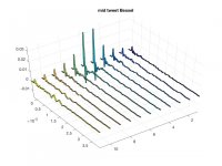
To see if I could identify the source of the narrowing at 5 KHz I just completed a set of nearfield measurements. I scanned the mic horizontally in 1 cm increments and at a height that placed the mic about one third of the way up the third panel (counting from the floor).
I made the measurements with six different settings.
The resulting impulse responses are attached in the order listed above. Note that the vertical scales vary while the time scale is fixed. The impulses make it clear that when only the tweeter is driven the diaphragm motion is pretty well restricted to the driven area (graph 3). When only the midrange is driven, and it's driven full range, there's a little bit of tweeter diaphragm motion (graph 2). When the midrange is low-pass filtered by a second order Bessel at 1 KHz (final graph) the whole diaphragm moves pretty much equally.
I haven't yet done any useful plotting in the frequency domain. I'm hoping that doing so will reveal the source of the 5 KHz directivity narrowing, which may not be super intrusive when listening to music but having seen it I'd like to know what it comes from.
Few
With Bolserst's assistance I had a good look at the directivity of the planar towers based on the angular impulse measurements I posted a bit ago. Those plots haven't been posted here (I don't want to post the product of someone else's labors!) but they seemed to show a few features of interest:
1) Overall, the directivity is fairly constant over +/-90 degrees and the range of frequencies accommodated by the necessary windowing.
2) In a very narrow frequency range around 5 KHz there's a narrowing of the directivity.
3) Above 5 KHz, up to maybe 15 KHz, the directivity gradually broadens; this is a fairly mild effect.
2) In a very narrow frequency range around 5 KHz there's a narrowing of the directivity.
3) Above 5 KHz, up to maybe 15 KHz, the directivity gradually broadens; this is a fairly mild effect.
To see if I could identify the source of the narrowing at 5 KHz I just completed a set of nearfield measurements. I scanned the mic horizontally in 1 cm increments and at a height that placed the mic about one third of the way up the third panel (counting from the floor).
I made the measurements with six different settings.
1) Midrange and tweeter both driven without equalization or crossovers
2) Midrange-only, no equalization or crossover
3) Tweeter-only, no equalization or crossover
4) Midrange and tweeter both driven; Bessel low pass on midrange, tweeter boosted with a shelf filter to compensate.
5) Midrange-only; Bessel low pass
2) Midrange-only, no equalization or crossover
3) Tweeter-only, no equalization or crossover
4) Midrange and tweeter both driven; Bessel low pass on midrange, tweeter boosted with a shelf filter to compensate.
5) Midrange-only; Bessel low pass
The resulting impulse responses are attached in the order listed above. Note that the vertical scales vary while the time scale is fixed. The impulses make it clear that when only the tweeter is driven the diaphragm motion is pretty well restricted to the driven area (graph 3). When only the midrange is driven, and it's driven full range, there's a little bit of tweeter diaphragm motion (graph 2). When the midrange is low-pass filtered by a second order Bessel at 1 KHz (final graph) the whole diaphragm moves pretty much equally.
I haven't yet done any useful plotting in the frequency domain. I'm hoping that doing so will reveal the source of the 5 KHz directivity narrowing, which may not be super intrusive when listening to music but having seen it I'd like to know what it comes from.
Few
Attachments
I should have clarified in my last post that the measurements spanned a width beyond the midrange conductor on both sides. In other words, the first and last line or two on each graph are from a region of the diaphragm that is not covered by conductor and not directly driven.
Few
Few
Thanks! Good to know!
I had hoped to have some frequency domain plots to post this evening but I've been too busy digging out from yesterday's winter storm and preparing for tomorrow's.
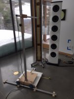
As a placeholder I'm attaching a photo of my newfangled microphone translation scheme---complete with ridiculously over-capable wheels (they're what I had handy). Two wheels are guided by a 90 degree angle piece of aluminum and the third wheel rides on the floor, but with an adjustable brake (so the thing doesn't roll uncontrollably).
It looks like overkill, and no doubt it is, but I've wasted too much time fiddling with microphone positioning with all these measurement series. I've found it much less frustrating to be able to position the mic precisely and reproducibly, even if it means investing some time building a device to make it possible.
Before building this thing I made four series of measurements like the ones I posted but had to throw them all away when I realized the mic had crept too close to the diaphragm for several of the scans. A couple of hours of work down the drain. If anyone decides they have a reason for doing a systematic series of measurements, my advice is to invest the time to build an apparatus that makes it easy to do the series without fidgeting with positioning. You'll be glad you did.
Few
I had hoped to have some frequency domain plots to post this evening but I've been too busy digging out from yesterday's winter storm and preparing for tomorrow's.
As a placeholder I'm attaching a photo of my newfangled microphone translation scheme---complete with ridiculously over-capable wheels (they're what I had handy). Two wheels are guided by a 90 degree angle piece of aluminum and the third wheel rides on the floor, but with an adjustable brake (so the thing doesn't roll uncontrollably).
It looks like overkill, and no doubt it is, but I've wasted too much time fiddling with microphone positioning with all these measurement series. I've found it much less frustrating to be able to position the mic precisely and reproducibly, even if it means investing some time building a device to make it possible.
Before building this thing I made four series of measurements like the ones I posted but had to throw them all away when I realized the mic had crept too close to the diaphragm for several of the scans. A couple of hours of work down the drain. If anyone decides they have a reason for doing a systematic series of measurements, my advice is to invest the time to build an apparatus that makes it easy to do the series without fidgeting with positioning. You'll be glad you did.
Few
Attachments
Regarding post 205.
An unconventional means of showing data.
So this is a heavily processed reading of an impulse response sent to the planar driver using a bandwidth limited signal?
The usual means is a directivity balloon. But I get the overall drift of what you are trying to show.
And I lika the mic stand!
An unconventional means of showing data.
So this is a heavily processed reading of an impulse response sent to the planar driver using a bandwidth limited signal?
The usual means is a directivity balloon. But I get the overall drift of what you are trying to show.
And I lika the mic stand!
Mark,
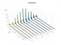
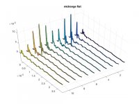
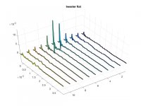
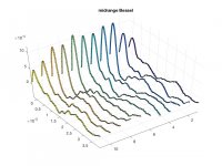
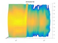
I agree post 205 includes an unconventional way of presenting the data. I used Matlab rather than one of the common audio software packages to do the analysis and make the graphs. However, I didn't do any data manipulation. They're straight plots of the impulse responses at different points in the nearfield in front of the diaphragm. The planars were driven full range (above 50 Hz) with the common exponential sine sweep from 20 to 20E3 Hz. The only filters applied were those I enumerated in post 205 (and again below, in this post).
I finally managed to fourier transform the impulse responses and present the results in a way that isn't impossible to interpret. The colormap spans about 25 dB. Frequency is along the horizontal axis and position along the width of the diaphragm is displayed along the vertical axis.
A reflection off the woofer tower, which I should have moved out of the way, corrupts the measurements labeled 10 and 11 cm. I'm hoping the distraction isn't a major problem. I've just finished the plots and haven't stared at them very long, but the cause of the 5 KHz necking in the directivity doesn't come screaming out at me. The plots seem to show that the expected parts of the diaphragm are active at the expected frequencies.
Few
I agree post 205 includes an unconventional way of presenting the data. I used Matlab rather than one of the common audio software packages to do the analysis and make the graphs. However, I didn't do any data manipulation. They're straight plots of the impulse responses at different points in the nearfield in front of the diaphragm. The planars were driven full range (above 50 Hz) with the common exponential sine sweep from 20 to 20E3 Hz. The only filters applied were those I enumerated in post 205 (and again below, in this post).
I finally managed to fourier transform the impulse responses and present the results in a way that isn't impossible to interpret. The colormap spans about 25 dB. Frequency is along the horizontal axis and position along the width of the diaphragm is displayed along the vertical axis.
1) Midrange and tweeter both driven without equalization or crossovers
2) Midrange-only, no equalization or crossover
3) Tweeter-only, no equalization or crossover
4) Midrange and tweeter both driven; Bessel low pass on midrange, tweeter boosted with a shelf filter to compensate.
5) Midrange-only; Bessel low pass
2) Midrange-only, no equalization or crossover
3) Tweeter-only, no equalization or crossover
4) Midrange and tweeter both driven; Bessel low pass on midrange, tweeter boosted with a shelf filter to compensate.
5) Midrange-only; Bessel low pass
A reflection off the woofer tower, which I should have moved out of the way, corrupts the measurements labeled 10 and 11 cm. I'm hoping the distraction isn't a major problem. I've just finished the plots and haven't stared at them very long, but the cause of the 5 KHz necking in the directivity doesn't come screaming out at me. The plots seem to show that the expected parts of the diaphragm are active at the expected frequencies.
Few
Attachments
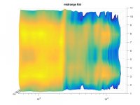
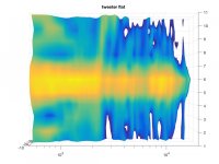
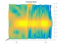
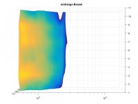
I should probably add a couple of comments on the most recent graphs so they can be interpreted more easily.
I didn't normalize the responses, even though that's sometimes done for a series of this sort. in each graph. In each graph, the eleven measurements were made at the eleven different positions along the width of a panel, and each measurement is presented "raw."
The colormaps are very similar from graph to graph but not absolutely identical. I decided to move the upper colomap limit up or down one or two dB if it made the pattern clearer, figuring nobody was going to be drawing quantitative data from the graphs. (I'll send you the impulse responses if you want to do your own quantitative comparisons.)
The graph that is closest to the way I've been running the speakers is attachment number 4. That graph has none of the equalization I've been applying except that the tweeter has the high shelf included in order to compensate for the Bessel low-pass applied to the midrange. Attachment 5 makes the impact of the low-pass filter quite clear---no high frequencies generated anywhere when only the midrange is driven.
Finally, maybe it's obvious, but I'll point out that in attachment 2 the double-ridge pattern is a result of the fact that only the midrange conductors are being driven--not the central tweeter. So the big gap running horizontally along the middle of the graph (at high frequencies) reflects the fact that the tweeter is turned off and only the midrange is being driven. But, since the "midrange" is being driven full-range (no Bessel low-pass) in this measurement, the diaphragm radiates high frequencies from the regions of the diaphragm that are directly driven.
Few
For those wanting more information on CBT arrays:
I came across a series of nine YouTube videos in which Don Keele (Mr. CBT) describes the background and performance of his CBT arrays. It's a bit long-winded but starting with video #6 there are interesting demonstrations of the performance of the arrays. It makes me wonder if a "planar" magnetic version could be constructed.
Few
THAT would be an interesting concept!It makes me wonder if a "planar" magnetic version could be constructed
Yeah, I think it would interesting as well. The trick would be getting the "planar" to follow the curve of the array, either intimately, or piece-wise. Stretching diaphragms across curved frames comes with some complications, as the curved ESL folks have demonstrated many times. It can be done but only if you apply tension only along the "straight" dimension. You also run into tension issues because unlike a truly planar diaphragm, one that's curved increases tension when it moves out but decreases tension when it moves toward the center of curvature.
With a 2 m tall speaker that spans 36 degrees vertically the radius of curvature wouldn't be overly small so maybe it could be made to work. In fact, as I envision it, the fact that the tension would be applied horizontally, across the short dimension of the diaphragm, would likely make it easier to implement than are curved ESL diaphragms that are tensioned vertically--along the long dimension.
There's also the question of whether to run resulting speaker as a dipole or enclose the backwave.
Few
How about push pull planar magnetic?
I happen to be working on something exactly like that.
It's well past the design stage. And I have done quite a bit of planar work in the past. So this is not a pie in the sky idea. I decided in December to make a no holds barred CBT. And the planar is a big part of it. I'm torn between using my smaller midwoofer or my 6.5" If I use the 6.5 you almost won't need a sub. That decision will influence the final planar design. Yes modeling is my friend on that account. Pattern control and diffraction is chief among what to look for in such a design.
The design tradeoffs on a planar are that a wider planar will have a degree of beaming just as FEW has measured. A narrower planar has the advantage of wider horizontal coverage before beaming. A wider planar can be crossed over lower than a narrow one. Same goes for woofers. A 5.25 has a pistonic range a little higher up than a 6.5. I guess if I put a front loaded horn into the rear of the loudspeaker you would be listening to full range sound again. A couple of long throw 8's would be a real butt kicker in that kind of an enclosure. Easily hit 18 hertz with near 100 db/watt.
So how to have my cake and eat it to? A true coaxial planar. Literally two drivers in the same assembly. A tall narrow nested in the middle of a wide one. But not coupled. Also not single ended. Not saying that it doesn't work in a single ended configuration. Few is listening and measuring such a design right now. But a push pull planar has the potential to be of higher efficiency. And that is the horse I am chasing.
All it takes is time and money.
Ah, so you've been holding out on us! Sounds like a very nice design.
I shied away from a symmetric magnet system because of magnet cost and assembly complications, but if you're looking to crank up the sensitivity it's clearly a good option. Share your progress, to the extent that your professional interests allow.
So will the planar portion be dipolar or enclosed-back?
Few
Sounds like a very nice design. I shied away from a symmetric magnet system because of magnet cost and assembly complications, but if you're looking to crank up the sensitivity it's clearly a good option. Share your progress, to the extent that your professional interests allow.
So will the planar portion be dipolar or enclosed-back?
Few
Ah, so you've been holding out on us!
I shied away from a symmetric magnet system because of magnet cost and assembly complications, but if you're looking to crank up the sensitivity it's clearly a good option. Share your progress, to the extent that your professional interests allow.
So will the planar portion be dipolar or enclosed-back?
Few
Keep an eye on my website. I'll trickle the information out there little by little.
As far as I have been able to think it through a CBT will not be as effective as a dipole. That radiation pattern is not what is in the mix for a successful CBT. Just watch video #9 by Don Keele. There is an explanation as to what and why on the driver selections.
As for holding out. I'm a driver/speaker designer. And a Consultant for other people and companies. If I tell you I gotta shoot ewe
As an example. High power planars have some weaknesses. And some strengths. The greatest weakness is the diaphragm giving out due to excessive heat. Even a 100db/watt driver is only 6% efficient. The other 94% of the power coming in gets turned into heat. So you need a higher temp diaphragm. Kapton has a higher melting temperature but tends to also have resonance difficulties. That I learned measuring and making AMT diaphragms a few years back. So you want something that is both high tem and high loss.
Let's say that I have found what I was looking for. But not gonna let that cat out of the bag.
Meow
- Home
- Loudspeakers
- Planars & Exotics
- DIY planar magnetic + open baffle woofer array