This is a little bit off the current subject and maybe has been discussed elsewhere but ...
I'm about to 'redo' my DH-220 mainly by simplifying the wiring and replacing the main power supply caps and wondered if there's any advantage in firstly using a C-R-C (6,800uF?) instead of the current simple 10,000uF C plus using discrete diodes and such things
The second idea was to fit separate diode bridges so each channel could have a separate C-R-C supply off the single secondary winding - will add a bottom case to hold the extra caps
Any suggestions ...?
This is a little bit off the current subject and maybe has been discussed elsewhere but ...
I'm about to 'redo' my DH-220 mainly by simplifying the wiring and replacing the main power supply caps and wondered if there's any advantage in firstly using a C-R-C (6,800uF?) instead of the current simple 10,000uF C plus using discrete diodes and such things
The second idea was to fit separate diode bridges so each channel could have a separate C-R-C supply off the single secondary winding - will add a bottom case to hold the extra caps
Any suggestions ...?
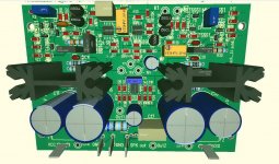
I replaced the power supply (except transformer) on my DH220 with a fully assembled power supply board I found on Ebay. It includes a bridge made of discrete TO220 rectifiers, each with a small heat sink, and six 10,000uF, 80V capacitors. Each rail thus has three 10,000 uF caps wired in parallel. I think I looked at the traces connecting the hot sides of the capacitors, and it looks like the (fat) trace can be broken and a small resistor inserted to arrive at a Pi reservoir capacitor arrangement. I don't think I ended up doing the Pi arrangement, but it looks like it can be done if there is enough space on the underside of the board for the series resistors (maybe 0.1-ohm 3W metal oxide film; they have a lower profile than sand resistors. One could probably put 2 in parallel if needed for more dissipation. It also has a 1uF film capacitor on each rail. I think it was not too expensive. It just fits in the area behind the transformer where the original caps and bridge were located. It has spade lug connectors.
Cheers,
Bob
Hello jameshillj,
i think Bob is talking about this one
1PCS 6x10000uF/80V High Quality Power Supply Board for Power AMP DIY | eBay
i think Bob is talking about this one
1PCS 6x10000uF/80V High Quality Power Supply Board for Power AMP DIY | eBay
Hello jameshillj,
i think Bob is talking about this one
1PCS 6x10000uF/80V High Quality Power Supply Board for Power AMP DIY | eBay
Yes, that is the one. A bit more expensive than I remember.
Cheers,
Bob
Thank you everyone for the great advice and thanks Guenther, Bob and 'tick' for the specific info about the eBay module - I have ordered one and will also add the Pi resistors and a primary series thermistor too
Many thanks - much appreciated - it's fascinating that this 'old guy' can so easily be put back into service and still do it's job so well
Many thanks - much appreciated - it's fascinating that this 'old guy' can so easily be put back into service and still do it's job so well
Hi all,
Is this worth doing on a dh-200 I have, does it make any audio improvement, I seem to need a bit more mid range in my amp though it sound good. what is a Pi resistor and why do we need a thermistor in the primary? I have a MOV in parallel with switch so I don't get a pop sound when turned on. Where can I get the input cap other than the non-polarize one in stock, I bypassed with a mica right now. Thanks again ALL
Is this worth doing on a dh-200 I have, does it make any audio improvement, I seem to need a bit more mid range in my amp though it sound good. what is a Pi resistor and why do we need a thermistor in the primary? I have a MOV in parallel with switch so I don't get a pop sound when turned on. Where can I get the input cap other than the non-polarize one in stock, I bypassed with a mica right now. Thanks again ALL
the switch contacts can be damaged during the closing for ON and during the opening for OFF.Add a soft start thermistor to save your power switch and diode bridge................
The OFF is by far the more damaging condition when some inductance is in the load.
Using a soft start does not prevent any of that OFF damage at the main ON/OFF switch.
Tell ticknpop to stop making up guidance that is misleading.
The soft start circuit does not protect or enhance the life of the main OFF switch.
It will have at best a marginal effect on the degradation of the contacts at ON operations.
The soft start circuit is to allow a transformer to start up reliably with a close rated fuse.
I have posted this information dozens of times.
I have explained what the resistor does for that start up current many times.
I have explained how the added resistor bypass relay contacts get exposed to ON and to OFF many times.
Last edited:
I'm a bit vague about this but I thought Hafler fitted a 'quenching' cap across the mains switch contacts to get around the problem
But, to recap - From your previous post, the turn OFF condition is the one that damages the power switch contacts regardless of what sort of soft-start turn ON device is used
So, the relay bipasses the series resistor on the mains active (after a short delay) on turn-on, but on turn-off, the power switch contacts open before the relay has a chance to drop out, so how does this avoid the damage to the switch?
I can't see any difference between a Soft Start resistor/relay delay cct and a simple series thermistor - maybe I'm missing something obvious ....
Hi all,
Is this worth doing on a dh-200 I have, does it make any audio improvement, I seem to need a bit more mid range in my amp though it sound good. what is a Pi resistor and why do we need a thermistor in the primary? I have a MOV in parallel with switch so I don't get a pop sound when turned on. Where can I get the input cap other than the non-polarize one in stock, I bypassed with a mica right now. Thanks again ALL
Hi,
Use a foil capacitor like WIMA MKP4 10µF (Audyn , Mundorf) or a Wima MKS2 10µF (same pitch) as input cap, alltimes better than an electrolytic.
I don't think that there is a MOV parallel to the switch, the partlist says 5nF/1000V disc capacitor.
The thermistor in the primary reduces in inrush current in the moment of switching on the amp.
The pi resistor is the resistor between the two + (-) pole of 2 paralleled power supply capacitors on the positive (negative) rail.
BR
Guenther
Hi Andrew,
In my many years of servicing, I have observed that devices using either the MOV or soft-start have power switches that far outlast units that don't use either. A unit that uses both protection methods would probably not need a new power switch until it mechanically wore out.
-Chris
Go easy man! ticknpop was correct about saving inrush surge damage to rectifiers, and I'll add capacitors. I feel it is a worthwhile addition to any amplifier designed with high storage capacitance. He is also correct in that it does save the power switch, and yes, there is the other effect from turn-off that it does nothing for.Tell ticknpop to stop making up guidance that is misleading.
To protect the power switch on turn-off, install an MOV across the primary of the transformer(s). It's that simple, and you didn't even suggest it. The MOV will also help protect the device in overvoltage events by turning on and blowing the primary fuse. Not absolute protection, but a lot better than nothing.The soft start circuit is to allow a transformer to start up reliably with a close rated fuse.
I have posted this information dozens of times.
I have explained what the resistor does for that start up current many times.
I have explained how the added resistor bypass relay contacts get exposed to ON and to OFF many times.
In my many years of servicing, I have observed that devices using either the MOV or soft-start have power switches that far outlast units that don't use either. A unit that uses both protection methods would probably not need a new power switch until it mechanically wore out.
-Chris
I use different resistance values depending on the normal maximum operating current of the transformer.
Low VA requires big resistance. I have used as high as 140r
High VA requires low resistance. I typically use 40r to 60r.
The same will apply to a Power Thermistor.
A CL60 does not suit small and medium transformer on a 220/240Vac supply.
They need much higher resistance to be an effective current limiter.
First attempt
The first attempt of Bob Cordell's DH-220C design adapted to the physical dimensions of the PC-25 board, built in the Hafler DH-120, is now in PCB production.
I am really interested, if and how it works .")
Thanks again Bob for a great work
BR
The first attempt of Bob Cordell's DH-220C design adapted to the physical dimensions of the PC-25 board, built in the Hafler DH-120, is now in PCB production.
I am really interested, if and how it works .
Thanks again Bob for a great work
BR
Attachments
- Home
- Amplifiers
- Solid State
- Hafler DH-200/220 Mods