English is not my mother tongue.
nor is it mine....but hey, we manage.....this is a diy forum where members
help each other out....
I totaly agree, AJT. The level of understanding, should not be an item on this forum.
Allegations of ignorance when we seeks help is nothing neighter I or other members like to be faced with. AJT, you have understood the "good spirit" of what is important on diyAudio.
It is a pity that not everyone have understood this.
Eivind S
Allegations of ignorance when we seeks help is nothing neighter I or other members like to be faced with. AJT, you have understood the "good spirit" of what is important on diyAudio.
It is a pity that not everyone have understood this.
Eivind S
Hi
I have one of these boards, I saw this thread and finally got around to trying mine. I think there is a problem.
As with the black board Liliya was asking about;
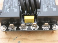
With all IO disconnected and testing between the two outer (relay switched) 220V neutral IO terminals = O.L (open circuit). Then testing between the inner two 220V Live IO terminals = 0.01 ohms, they are directly connected. Finally testing between each of the neutral and live terminals = O.L (open circuit).
With power off, the 220V in and the LED-low voltage switch connected I see the same results as with all IO disconnected.
With power on, the 220V in and LED-low voltage switch connected and low voltage switch deactivated I got 238V on both the high voltage input and output. Then power on, 220V in, LED-low voltage switch connected, and with low voltage switch activated I also got 238V on both the high voltage input and output.
However, with power on, 220V input and output connected to a toroidal transformer, the LED-low voltage switch connected but deactivated the output dropped to 108V.
Finally, the same configuration, this time with the low voltage switch activated I got 238V on both the high voltage input and output.
It looks like the relay switching thermistor circuit is working but when the unit is switched off there is still a circuit between the 220V IOs which shows as 238V but drops to 108V when there is a load on the output.
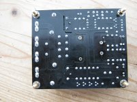
As far as I can tell the relay-thermistor circuit looks correct. However, looking at the pcb I can only find 2 other ways power could flow from the input to the output when the relays are deactivated. The first are the transformer 220V + - traces, I took the transformer off and checked the traces, all appears to be good.
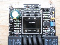
The second is the small yellow capacitor situated between the relays on the 220v IO end of the board. It is a MKP X2 0.047uF 275V ac cap and is positioned across the (relay switched) 220V neutral in and out terminals. MKP X2 capacitor 0.047uF/275VAC, View X2 0.047uF, TENTA (TC) Product Details from TENTA ELECTRIC INDUSTRIAL CO., LTD. on Alibaba.com
I figured the cap would be for noise reduction/filtering so I removed the cap and tested (with inline bulb tester), the problem is gone, there no voltage on the 220V out terminals when the unit is turned off.
Am I on the correct path here? If so, I would appreciate some ideas about how this is happening and how to resolve it.
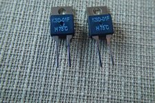
P.s. The relays are HJQ-15F-S-H (http://www.quartz1.com/price/PIC/160Q0761401.pdf Page 63) and the only info on the thermistors is NTC 20D-20 which I think means they are 20 ohms in a 20mm case
Regards.
I have one of these boards, I saw this thread and finally got around to trying mine. I think there is a problem.
As with the black board Liliya was asking about;
With all IO disconnected and testing between the two outer (relay switched) 220V neutral IO terminals = O.L (open circuit). Then testing between the inner two 220V Live IO terminals = 0.01 ohms, they are directly connected. Finally testing between each of the neutral and live terminals = O.L (open circuit).
With power off, the 220V in and the LED-low voltage switch connected I see the same results as with all IO disconnected.
With power on, the 220V in and LED-low voltage switch connected and low voltage switch deactivated I got 238V on both the high voltage input and output. Then power on, 220V in, LED-low voltage switch connected, and with low voltage switch activated I also got 238V on both the high voltage input and output.
However, with power on, 220V input and output connected to a toroidal transformer, the LED-low voltage switch connected but deactivated the output dropped to 108V.
Finally, the same configuration, this time with the low voltage switch activated I got 238V on both the high voltage input and output.
It looks like the relay switching thermistor circuit is working but when the unit is switched off there is still a circuit between the 220V IOs which shows as 238V but drops to 108V when there is a load on the output.
As far as I can tell the relay-thermistor circuit looks correct. However, looking at the pcb I can only find 2 other ways power could flow from the input to the output when the relays are deactivated. The first are the transformer 220V + - traces, I took the transformer off and checked the traces, all appears to be good.
The second is the small yellow capacitor situated between the relays on the 220v IO end of the board. It is a MKP X2 0.047uF 275V ac cap and is positioned across the (relay switched) 220V neutral in and out terminals. MKP X2 capacitor 0.047uF/275VAC, View X2 0.047uF, TENTA (TC) Product Details from TENTA ELECTRIC INDUSTRIAL CO., LTD. on Alibaba.com
I figured the cap would be for noise reduction/filtering so I removed the cap and tested (with inline bulb tester), the problem is gone, there no voltage on the 220V out terminals when the unit is turned off.
Am I on the correct path here? If so, I would appreciate some ideas about how this is happening and how to resolve it.
P.s. The relays are HJQ-15F-S-H (http://www.quartz1.com/price/PIC/160Q0761401.pdf Page 63) and the only info on the thermistors is NTC 20D-20 which I think means they are 20 ohms in a 20mm case
Regards.
Attachments
Last edited:
Bobsone
Interesting what you have found out. The "big question" for me has been the same as you have observed:On 220V out on the PCB, the full main voltage is still there after the momentary switch is pulled to OFF. I find that strange and it not what I want from a Power Starter. You have removed one cap. If this is the right "medicine", I hope that some members with the right teoretic backgrond can comment.
I have sent a mail to the seller of this unit, but I am not suprised that the only thing in return, was the same "documentation" as we find on the sellers webside.
Eivind S
I figured the cap would be for noise reduction/filtering so I removed the cap and tested (with inline bulb tester), the problem is gone, there no voltage on the 220V out terminals when the unit is turned off.
Am I on the correct path here? If so, I would appreciate some ideas about how this is happening and how to resolve it.
not strange at all......
with that yellow cap shunting the thermistors in there,
it is but natural to measure voltage at the output side....
removing that cap will not hurt anything either...
that cap serves as spark suppressors to help prolong the
life of relay contacts...a 0.001ufd 1 or 2kV disk ceramic cap is better imo...
The Power Thermistors must be between either the Live IN and Live OUT, or between the Neutral IN and Neutral OUT.
From what AJT could read from the traces your unit should have these added resistances in the Live to Live and you should be able to measure that resistance.
I wonder if the capacitor had gone faulty and was shorting between the two Live connectors?
Now with the cap removed, can you measure the Live to Live resistance with the unit disconnected from everything?
The capacitor from Live to Neutral must be an X rated type
If there are any capacitors from Live to PE, or from neutral to PE they must be Y rated.
...........
..........
The second is the small yellow capacitor situated between the relays on the 220v IO end of the board. It is a MKP X2 0.047uF 275V ac cap and is positioned across the (relay switched) 220V neutral in and out terminals. MKP X2 capacitor 0.047uF/275VAC, View X2 0.047uF, TENTA (TC) Product Details from TENTA ELECTRIC INDUSTRIAL CO., LTD. on Alibaba.com
Regards.
That capacitor is why you read unexpected voltages. Its impedance at 50/60Hz is much lower than your DMM's input impedance, so the DMM sees almost a full mains voltage when there are no other loads. Yet it is not low enough to pass the full voltage when some load is attached.
Hi
Thanks for the replies.
AJT
Thanks for the input, I have started looking at spark suppression – snubber info online. It seems odd that they only included 1 capacitor rated at only 275V, not a lot of headroom, I have seen a number of people stating the cap should be 2 - 4 times the voltage.
Andrew
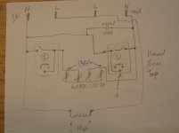
I have included a diagram of the in – out end of the board. The Power Thermistors and relays are on the Neutral IN – OUT line. Thanks for the X – Y rated capacitor info, there aren’t any other caps on the 220V IO traces, they just had the one 275V X2 cap sitting across the relay on the neutral line.
I can only test capacitance with my DMM and from a capacitance view it appears good but resistance is an unknown.
Nattawa
Thanks for clearing that up, I thought the dropping to 110V(ish) when under load was a bit of a puzzle. I measured the toroid transformers secondaries and they were showing 50% of the normal output, I doubt that kind of brown out would help downstream components.
Am I correct in thinking that in the long term, replacing the cap is better than leaving it out?
The ? on the schematic is because although that pin isn’t soldered it is permanently connected to the Neutral in terminal and sits outside the high voltage area of the board.
Regards.
Thanks for the replies.
AJT
Thanks for the input, I have started looking at spark suppression – snubber info online. It seems odd that they only included 1 capacitor rated at only 275V, not a lot of headroom, I have seen a number of people stating the cap should be 2 - 4 times the voltage.
Andrew
I have included a diagram of the in – out end of the board. The Power Thermistors and relays are on the Neutral IN – OUT line. Thanks for the X – Y rated capacitor info, there aren’t any other caps on the 220V IO traces, they just had the one 275V X2 cap sitting across the relay on the neutral line.
I can only test capacitance with my DMM and from a capacitance view it appears good but resistance is an unknown.
Nattawa
Thanks for clearing that up, I thought the dropping to 110V(ish) when under load was a bit of a puzzle. I measured the toroid transformers secondaries and they were showing 50% of the normal output, I doubt that kind of brown out would help downstream components.
Am I correct in thinking that in the long term, replacing the cap is better than leaving it out?
The ? on the schematic is because although that pin isn’t soldered it is permanently connected to the Neutral in terminal and sits outside the high voltage area of the board.
Regards.
Attachments
Last edited:
your diagram can't be right.
Compare to post40.
X and Y rated capacitor are intended for mains duty. they are rated for AC voltage. When you see 275V, X2 it actually means 275Vac X rated.
Most capacitors are rated for DC, but state xV, instead of xVdc
Some will state xVac
And some will state xVdc, yVac, making it very clear what voltage rating apply.
You have to read the ratings carefully to ensure you are selecting the correct component.
Last edited:
Hi
.........
Am I correct in thinking that in the long term, replacing the cap is better than leaving it out?
The ? on the schematic is because although that pin isn’t soldered it is permanently connected to the Neutral in terminal and sits outside the high voltage area of the board.
Regards.
What did you have on the secondary side of the power trans when you had the "110v-ish" reading? If the secondary was open circuit then the only load was the iron loss of the power trans, which is quite a light load that can explain the "brown-out" voltage you saw.
The purpose of that capacitor is to suppress the sparks at the instance the relay contact opens to break a large current for a prolonged life of the relay. If you're concerned about the residue voltage from the capacitance you can use a ceramic one with high voltage rating, 0.01uF/1KV or 2KV, as mentioned in other posts before. The reduced capacitance (1/5) can make the brown-out 5 times "darker"
")
Hi
The ? on the schematic is because although that pin isn’t soldered it is permanently connected to the Neutral in terminal and sits outside the high voltage area of the board.
Regards.
There are 5-pin and 4-pin varieties of that popular 30A relay, the PCB was designed to suit both. The un-soldered 5th pin on your board is supposed to have a slot around it to suffice the creepage distance towards the secondary side of the circuit, as it is permanently connected to the mains circuit inside the relay package.
I designed a similar soft-starter PCB that uses the 4-pin package relay only just to avoid the trouble of cut a slot. Pics Here
By the way, I don't like they parallel up the NTC thermistors, as it encourages current hogging -- the one heats up faster conducts most all the current. Two of them would end up doing most of the work while the other two stay cool and do little to nothing.
Since both me and a friend of mine have a couple of this unit, the "big question" for us is:Can it be "modded" for safe use in an amplifier, or is the bin laden the right place to put this unit?
What must be done if the unit should work properly (and safe). Changing the yellow cap has been mention. What will be a good replacement.
Nattawa, you dont like the parallel NTC thermistors. I have seen this argument in other threads here on diyAudio, that paralleling is a "bad thing" in a circuit like this. Can this problem been solved on this PCB?
It is a pity if four of this Soft Starter ends up as trash for me and my friend.
Eivind S
- Status
- This old topic is closed. If you want to reopen this topic, contact a moderator using the "Report Post" button.
- Home
- Amplifiers
- Power Supplies
- Soft start question