Maybe not for human
I am still thinking how a 200kHz pwm class D can produce good full range amp.
I dont know about lot about class D but it working perfectly
I dont know about lot about class D but it working perfectly
Usually for me, for full range at least 300kHz for PA and 350kHz for indoor.
Usually for me, for full range at least 300kHz for PA and 350kHz for indoor.
y u dont try 200khz amplifier as full range amp
you follow only thiory try it practically
you dont believe this is clear sound at max volume
sound desort camara recording problem
what about this
https://www.youtube.com/watch?v=umKeO7uNWLc
Hey, theoretical smart guy of this topic. Stop bluffing! If your card doesnt give 20kHz , then the square wave cannot have harmonics above 20kHz [emoji12] .
(Thank you for the unreasonable personal attack!)
Obviously. This doesn't have to be mentioned.
What's your problem exactly? Proove where I bluffed!
PS What a constructor are you ? If you dont have a simple signal generator?[emoji33]
Now I have. At the time when I evaluated this amp I didn't have near hand. And I didn't care much how it react to a signal that will never be applied. It follows any audio signal. Thats enough. Or do you think 0...20 kHz +/- 1 dB transmittion is not enough?
I am a constructor who knows what is needed for a task. I developed analog HBO decoder without any instruments on a boring evening.
No difference. All principles are the same for any size. OK, above 2 kW other topologies and methods worth to be considered. I built some with 150V and 30A continuous output and 200 kHz switching freq about 8 years ago, and they were almost the same quality as the smaller ones. Instead of 0.1 % it has 0.3 % THD, but not 3 %! Others make 50 kW in one rack unit and much better quality. That is a big amp. We are nothing.
The amp I did refere to was a big amp, this power comparator is also be on diyaudio some time ago, I do not understand what is now fast enough, the bigger the mosfet the bigger the gate capacitance you need a beefy driver to get high up and fall times.
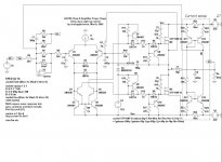
picture is one from @analogspiceman 2005, so a long time ago it is a hysteric window type amp. also from the Phillips datasheet.
But this is now 1200 watts, there is a need of a cery fast power stage with very high fall and risetimes to get low EMI and efficienty.
Attachments
Do you Iraudamp1?
Please learn English! This sentence has no meaning.
And as usual this is only one of the many mistakes you made. Iraudamp uses IR2011S, not IR2110
http://www.irf.com/technical-info/refdesigns/iraudamp1.pdf
And its input is not a comparator made of LTP like yours, but a 2nd order integrator made of OPA. It's loop gain is independent from input source, not like in your! Its offset current is negligible, not like in yours. An other difference is that you can not change its input, it must be inverting. So basically it is totally incomparable to your schematic. Nothing is in common regarding input.
I dont know your problem
Invert or not is a choice. Pro con always there. But you cannit say that is wrong.
Please don't lie! I never wrote it was wrong! I wrote the other way would be better. Do you really think you have the right prohibiting improvement advices???
Anyway show your real working amp please
Not just always blaming other but no real working amp
Do you really think photos made of amplifiers can change rules of electronics???
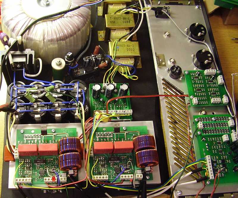
This is my 150V 30A amp inside, during assembling (3 versions were developed, this was the first):
This is my simple UcD version:
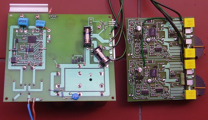
This is a bridged amp based on TL494:
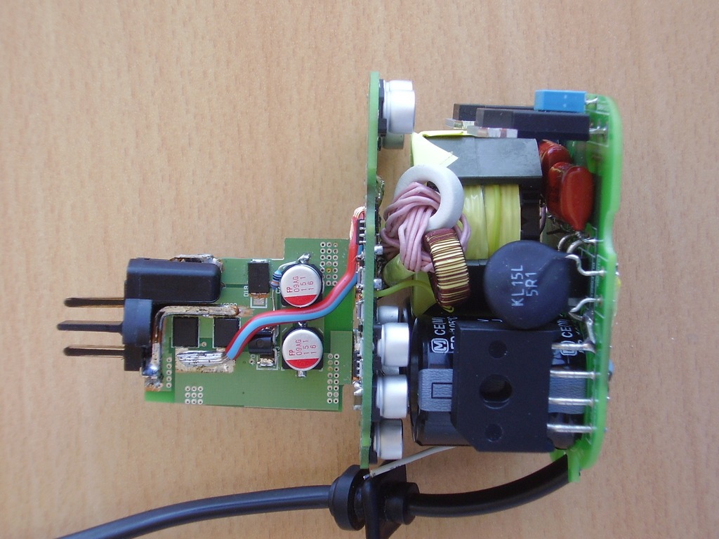
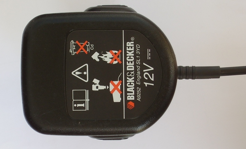
This is a 230V/12V 30A SMPS built inside the case of a drill battery:
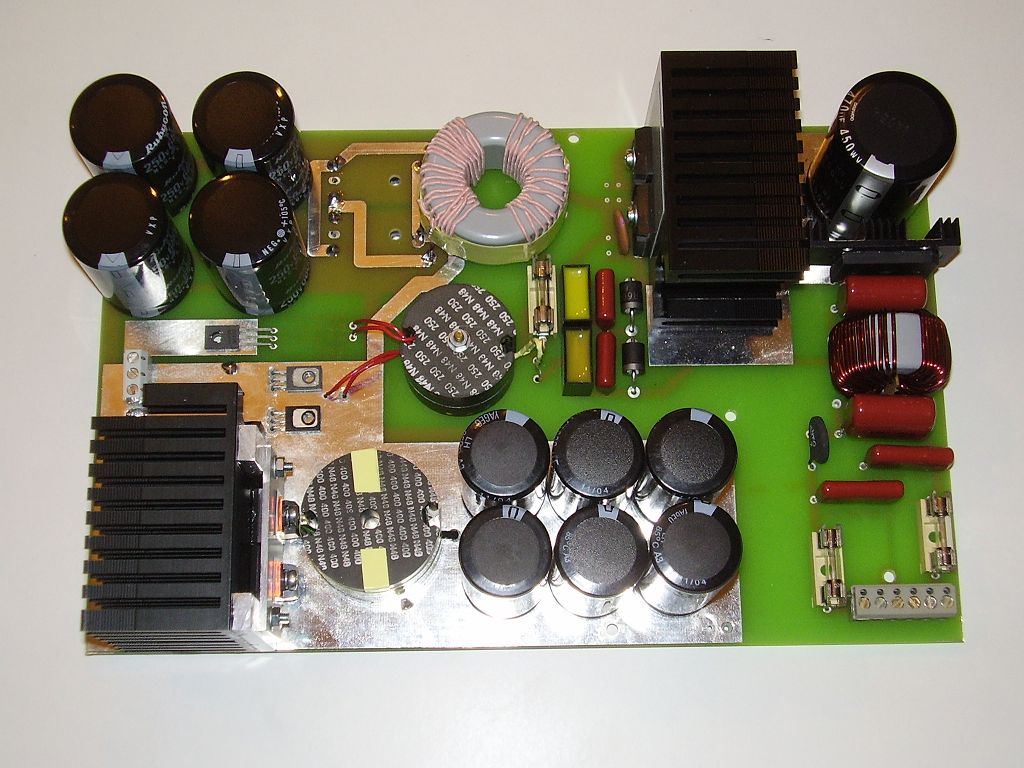
800 W PSU + 2*400W fullrange amp:
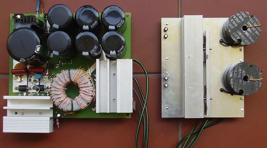
This is my smaller, 1 kW complete sub amp (PSU, amp, preamp, LPF):
And this is the bigger one:
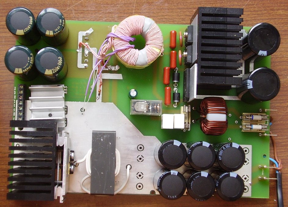
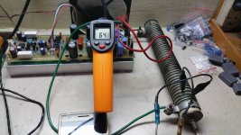
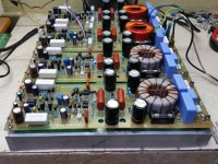
2 kW at 2 ohms, full bridge, 3 level PWM, post-filter feedback, overcurrent measuring on Rds-on (tested with 7 pcs of 18" Eminence Omega woofer in parallel, +/-63V PSU, stayed cold):
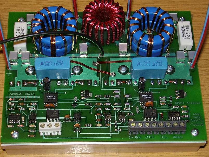
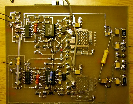
This is a very high speed UCD (a little tuning was made on PCB):
These are only the pictures already uploaded here, since I'm not home, I can show only this much, but I've built about 50 ClassD amps. All of them were designed entirely by me, I never copy schematics.
Are you satisfied now? These pictures are irrelevant, trueth and logic speaks for itself if the listener is able to think. Stupid errors in schematics also speakes for themself.
Last edited:
Delay is for individual component i.e. delay on or off.
What a delay in an amp?
Are you creating sound effect or something?
The delay of power comparator section. It is written in the article linked by Kees. Read it before stating nonsense. This is very simple and essential knowledge regarding self-oscillating amps. Without it you can not understand how to design them correctly.
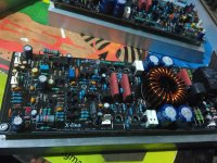
Thanks kartino!And this is latest D2KNeo Schematic
I do not sell anything so then I feel free to give all of mine. Except PCB is not done by me so then I have no right to share.
Let's wait the maker of pcb to share with us
The amp I did refere to was a big amp, this power comparator is also be on diyaudio some time ago, I do not understand what is now fast enough, the bigger the mosfet the bigger the gate capacitance you need a beefy driver to get high up and fall times.
I don't understand what you don't understand. ("now fast enough"? who said this, and about what?) There are both beefy drivers and low capacitance FETs.
picture is one from @analogspiceman 2005, so a long time ago it is a hysteric window type amp. also from the Phillips datasheet.
But this is now 1200 watts, there is a need of a cery fast power stage with very high fall and risetimes to get low EMI and efficienty.
This? Where do you see this was 1200W? Not actual schematics, but principles stays the same. Need high fall and rise time to get "efficienty"? Or "low efficienty"? I don't understand your sentence. High efficiency and low EMI are contradictional requirements in this field. I don't know what are you trying to tell.
This is my 150V 30A amp inside, during assembling (3 versions were developed, this was
Sorry Pafi,
I have seen many transformer sized like that.
Do you think that is 4.5kW transformer?
And for UcD. So you are talking a tiny UcD.
Why only hundred kHz.
Why not MHz?
I understand now what you are talking about.
Please learn English! This sentence has no meaning.
And as usual this is only one of the many mistakes you made. Iraudamp uses IR2011S, not IR2110
http://www.irf.com/technical-info/refdesigns/iraudamp1.pdf
And its input is not a comparator made of LTP like yours, but a 2nd order integrator
So you learn personal attack from people typo?
I am not talking the gate driver type but the concept is the same idea. Whether use op amp or discrete, 2nd order or not, THE FEEDBACK is the same! LTP, OTA or not the feedback do the same.
You talk different detail, of course they are different, one is voltage mode the other current mode.
Last edited:
Please don't lie! I never wrote it was wrong! I wrote the other way would be better. Do you really think you have the right prohibiting improvement advices???
Oh yess... you did not say I am wrong
You said the schematic was just like placing brute force component without knowing it!!!
Right Pafi?
So you learn personal attack from people typo?
This is not typo. The meaning of the sentence was missing completely, not only some letter. And it is not about your person, but about your posts.
I am not talking the gate driver type
IR2110 IS a gate driver, and this was the ONLY information over "IR" to specify which amp you think about. You can't expect to understand if more than 50 % of the info you provide is incorrect.
but the concept is the same idea. Whether use op amp or discrete, 2nd order or not, THE FEEDBACK is the same! LTP, OTA or not the feedback do the same.
Totally not. You have no idea how these feedbacks work if you think they do the same. Try making a quantitative analysis! On OPA inverting input there is virtual GND. On LTP inverting input there is the switching freq residual required to maintain oscillation and modulation. Bias currents are also totally differents. Nothing is the same. Even in the audio range there is significant difference.
You talk different detail, of course they are different, one is voltage mode the other current mode.
I guess you mean LTP output is current. This is the difference that absolutely not important. The input of LTP is still voltage controlled, the output is irrelevant in this aspect.
Pafi,
I am not talking the individual Op amp or discrete LTP. You are missunderstand just because you think you too smart. I am talking about whole feedback loop. However you stuck on how it works for Op Amp vs Discrete.
Again, I was had problem typo by missing to put word "know" in the sentence because my smartphone problem.
So then IR2110 is a gate driver
What about IR2011?
Last edited:
y u dont try 200khz amplifier as full range amp
you follow only thiory try it practically
you dont believe this is clear sound at max volume
sound desort camara recording problem
what about this
https://www.youtube.com/watch?v=umKeO7uNWLc
What a theory without practice, and just talking?
I have been ten years practice.
I stated that frequency is for FULL RANGE
For sub even 100kHz can be as many big company build sub amp. And make sub amp is much much easier compared to make full range amp.
Usually for me, for full range at least 300kHz for PA and 350kHz for indoor.
Last edited:
- Home
- Amplifiers
- Class D
- UCD 25 watts to 1200 watts using 2 mosfets