Did you make sure the pinout was correct for the 2N551? They have a different pinout than the BC547.I tried attaching a few pics, but it says it cant be processed because of some security token missing.
Anyway,Mr.Mile,
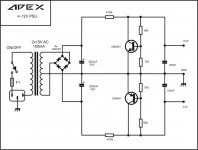
I have a few doubts in your +/- 12 VOLT ps with 2n5551,2n5401. I built it and got + 0/-16 volt, with the specified components. I replaced the 2n5551 with another one, and it remained the same. I then replaced the same with BC547 and this time i got +16/-15 volt. My doubts are
1.Why i could not get 12 volt ?
2.Anything wrong in my transistor substitution?
3.Is it okay to use this for a tB3 since they are not symmetrical?
Thanks in ADVANCE Mr.Mile. Your help is appreciated.
Did you make sure the pinout was correct for the 2N551? They have a different pinout than the BC547.
Yes.Mr.Terry.I checked the pinout from datasheet before soldering.Thanks
Mr.Mile, This schematic I found in your facebook post,not in Diyaudio.
Thanks and regards.
Use 1k pot and 2k7 resistor in series connect instead 3k3 resistor and you can set voltage.
Regards
Measure voltage across one of the big power resistors with a DVM. Adjust the bias trimpot (1 of 2 and one near the middle next to BD139) and measure voltage across the 0.47R (2 in parallel so R effective is 0.47R/2). Adjust between 80mA and 200mA. 150mA is a good trafeoff beyween heatboutput and low distortion). Other pot adjust to get 0vdc at output terminal.
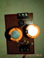
I currently use my old CT transformer with 15VAC output , I get about +22.2 VDC and - 22.2 VDC. Is it okay? I set the current to ~ 100mAh and after 15 minutes, the current is drop to ~ 93mAH. And after 30 minutes it stay about ~ 92mAh. Is it normal? The heatsink still cold after 30 minutes.
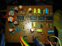
I love this amp! The sound is better than myRef, better than LM1875 and absolutely better than TPA3116 . I can hear the high tone is better than myRef amp. Very dynamic sounding. The bass is wooow

Thank you very much Mr. Mile for the design, Mr. Xrk971 for the mods, and Mr. Sonal Kunal for the pcb
I currently use my old CT transformer with 15VAC output , I get about +22.2 VDC and - 22.2 VDC. Is it okay? I set the current to ~ 100mAh and after 15 minutes, the current is drop to ~ 93mAH. And after 30 minutes it stay about ~ 92mAh. Is it normal? The heatsink still cold after 30 minutes.
I love this amp! The sound is better than myRef, better than LM1875 and absolutely better than TPA3116 . I can hear the high tone is better than myRef amp. Very dynamic sounding. The bass is wooow
Thank you very much Mr. Mile for the design, Mr. Xrk971 for the mods, and Mr. Sonal Kunal for the pcb
Glad you like it. (I think we are talking about FH9 right or is it FH12?). That is kind of on low side for voltages and hence why it runs cool. The bias currents in the various stages are probably low due to lower voltage. Mr Mile may be able to suggest alternative resistors for 22v rails. It will sound even better with 35v supply.
It is FH9 with BD139 BD140. After 2 hours, temperature of heatsink is just ~42 - 43°C. I tried to set bias current higher ~200mA, but I can't hear the difference. the heatsink is too hot, around ~68°C. I can't touch more than 5s. I set the bias current back to 100 mA
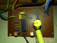
P30ZF preamplifier PCB layout ,not tested .....
Regards,Alex
alex mm, would you kindly post the gerber files for this pre-amp?
I don't wish to get really good boards like pinnocchio is ordering.
If it isn't too much, maybe the A40 one as well! = )
Cheers,
b
Last edited:
Hello everyone
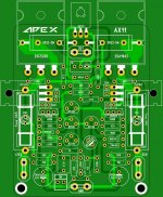
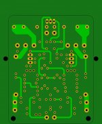
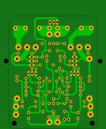
For fun I drew a layout of the AX11 amplifier based on the miniamp with some small modifications to facilitate setting up on the heatsink.
I checked the connections and there is no error but I do not know yet if I will make this amplifier.
If the gerber or .lay6 files are of interest to someone, I will make them available.
Attachments
Hello everyone
For fun I drew a layout of the AX11 amplifier based on the miniamp with some small modifications to facilitate setting up on the heatsink.
I checked the connections and there is no error but I do not know yet if I will make this amplifier.
If the gerber or .lay6 files are of interest to someone, I will make them available.
Nice work.
Regards
Sprint layout 6 file with schematic.Project16,
I would be interested in the .lay6 files.
Attachments
Mr. Mile, wish you a very very happy new year, i wish you keep on giving nice little circuits the whole year, thanks,
reg
prasi
Thank you for your contributions on this thread.
Regards
- Home
- Amplifiers
- Solid State
- 100W Ultimate Fidelity Amplifier