Hi, Bob!
Unfortunately, the last cascade VAS, even very carefully designed, making from 20 to 50 dB more distortion, than the follower output. To reduce these distortions need much loop gain, which usually nobody pays attention to it. From crossover distortion is fairly easy to get rid of reducing inductance in the emitter circuits of output transistors, where many people do use a ceramic wire wound resistors with high inductance.
I'm afraid I must disagree.
Try this:
Center-tap the driver emitter resistor that straddles the PNP and NPN drivers. Take the global feedback from this node instead of the output node and measure the amplifier's distorion, while there is no load applied to the output stage (or the output stage is disconnected entirely). Compare this to the distortion of the amplifier when it is connected conventionally, and with an 8 ohm load. The greater distortion in the latter measurement will show you how much (significant) distortion is added by the output stage. You will also notice much more pesky high-order harmonics when the output stage is included, a straightforward result of crossover distortion.
BTW, if you measure the distortion at the center-tapped driver emitter resistor node when the amplifier is operating conventionally, you will see a very good approximation to the open-loop output stage distortion (the distortion waveform will be inverted.
I do not use wirewound output stage emitter resistors, "non-inductive" or not. I use metal oxide film (MOF) resistors. In many cases, a 3W resistor is enough, but they can be paralleled if necessary.
Cheers,
Bob
I do not use wirewound output stage emitter resistors, "non-inductive" or not. I use metal oxide film (MOF) resistors. In many cases, a 3W resistor is enough, but they can be paralleled if necessary.
Cheers,
Bob
Why to use metal oxide (there is no better then 5%) when is better to use metal film, 2W is easily available. U use two in parallel in my CF power amp.
Best wishes
Damir
Attachments
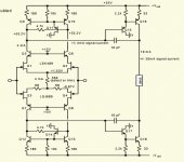
Bob, I replaced in Cordell PA(Fig 3.10_p.85)-3.asc the transistor followers on idealized followers E1. Cascade with a common emitter (point Q13B), as before, contributes 1.6% distortion. Band width distortion at the level of -120 dB: 140 kHz.
In the original model (Cordell PA(Fig 3.10_p.85)-2.asc) follower output (bQ27) introduced 0.036%, however, 10 times wider frequency range.
An externally hosted image should be here but it was not working when we last tested it.
In the original model (Cordell PA(Fig 3.10_p.85)-2.asc) follower output (bQ27) introduced 0.036%, however, 10 times wider frequency range.
Attachments
Last edited:
Why to use metal oxide (there is no better then 5%) when is better to use metal film, 2W is easily available. U use two in parallel in my CF power amp.
Best wishes
Damir
That's fine, too. No need for better than 5% tolerance for RE.
Cheers,
Bob
Burning Amp DH220C Slides
Some folks expressed interest in seeing the slides from my Burning Amp 2016 presentation of the Hafler DH220C revamp using a full-complementary JFET input stage with a floating tail. It is a powerpoint file, and, unfortunately, it is over 7 MB, even zipped (zip compression of ppt files is negligible). I don't know of any easy way to post it here. Please email me if you would like a copy.Here it is as an attached zip folder.
Cheers,
Bob
Here is Bob Cordell's Burning Amp 2016 slide deck, converted into Acrobat (.pdf) format.
Thanks Mark!
Cheers,
Bob
Thanks Bob for the slides, and Mark for posting them.
+1 to that!
And thank you all, for the discussion in this thread to date. Much useful input posted, to think about and work with.
Thanks, Mark.Here is Bob Cordell's Burning Amp 2016 slide deck, converted into Acrobat (.pdf) format.
But I do not agree with some definitions:
An externally hosted image should be here but it was not working when we last tested it.
This current can be stabilized at a predetermined value.
An externally hosted image should be here but it was not working when we last tested it.
http://i.fpicture.ru/img/2016-12/29/58657717e7d15a5022456813.png
The model is attached.
An externally hosted image should be here but it was not working when we last tested it.
Unfortunately, I have not reached this poweramp the Lich of great depth NFB at a frequency of 20 kHz. Here only 90 dB. But linearity is not going to be very bad.
An externally hosted image should be here but it was not working when we last tested it.
I will be happy if that dirty trick will help someone.
")
Attachments
Last edited:
Thanks, Mark.
But I do not agree with some definitions:
An externally hosted image should be here but it was not working when we last tested it.
This current can be stabilized at a predetermined value.
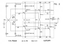
Numerous examples of stabilizing the "shoot through" current are around, Monticelli and Gosser have several patents going back to the 80's. That's also not Bob's final circuit where the current is defined .
Last edited:
I'd be grateful for links.Numerous examples of stabilizing the "shoot through" current are around, Monticelli and Gosser have several patents going back to the 80's. That's also not Bob's final circuit where the current is defined .
I'd be grateful for links.
Mark you should have filtered the list to the ones that are applicable. Here is one from Gosser on the two stage CFA which as they say is obviously applicable to a VFA.
Attachments
More to the point Bob's final input stage is fine, the 4.7k resistors soak up the inevitable offset currents without causing large changes in the common mode bias current. It is easy to be fooled, the first circuit might even simulate because all components are perfectly matched. Rolling the numbers here 10mA standing current is about right for 180 Ohm vs 33 Ohm emitter resistors and 2mA in the input stage (there are a few small corrections necessary).
Attachments
Thanks, Mark.
But I do not agree with some definitions:
An externally hosted image should be here but it was not working when we last tested it.
This current can be stabilized at a predetermined value.
An externally hosted image should be here but it was not working when we last tested it.
http://i.fpicture.ru/img/2016-12/29/58657717e7d15a5022456813.png
The model is attached.
An externally hosted image should be here but it was not working when we last tested it.
Unfortunately, I have not reached this poweramp the Lich of great depth NFB at a frequency of 20 kHz. Here only 90 dB. But linearity is not going to be very bad.
An externally hosted image should be here but it was not working when we last tested it.
I will be happy if that dirty trick will help someone.
There are indeed numerous ways to stabilize the VAS bias current in that arrangement, some more complicated than others. Mine is just one of the simpler ones
.Cheers,
Bob
Wondering Bob what you used for the distortion plots on the Hafler mod,
did you use a sound card based system or something else?
I assume that the data is on your PC with not a lot of effort, or would that
not be correct.
Hi Pete,
I actually made the THD measurements manually using my THD analyzer. I then created the plots in VISIO. An ordinary sound card would not normally be able to adequately capture the harmonics of fundamentals up to 20kHz.
Cheers,
Bob
Thank you very much. There are many interesting things.
- Home
- Amplifiers
- Solid State
- Bob Cordell's Power amplifier book