I'm building current sources and current mirrors that run at about 8mA of bias, and trying to decide which device types to select. Among the criteria I have considered, is the Early Voltage (SPICE parameter "VAF"), which determines the output conductance, the "flatness" of the Ice vs Vce curves.
I plopped a bunch of PNP thru-hole transistors on the curve tracer and found to my surprise, that they didn't match up to the Early voltage measurements in The Art Of Electronics 3rd Edition, Table 8.1a, page 501.
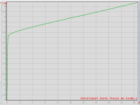
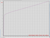
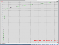
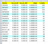
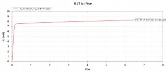
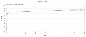
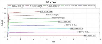
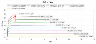
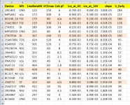
Here's a spreadsheet showing my measured values, in the vicinity of 8 milliamps Ice. And a few raw curve tracer pictures too. Hover your mouse over the image to read the part number; it's embedded in the file name.
I was slightly surprised and disappointed that the BC560 and BC327 were so crummy.
_
I plopped a bunch of PNP thru-hole transistors on the curve tracer and found to my surprise, that they didn't match up to the Early voltage measurements in The Art Of Electronics 3rd Edition, Table 8.1a, page 501.
Here's a spreadsheet showing my measured values, in the vicinity of 8 milliamps Ice. And a few raw curve tracer pictures too. Hover your mouse over the image to read the part number; it's embedded in the file name.
I was slightly surprised and disappointed that the BC560 and BC327 were so crummy.
_
Attachments
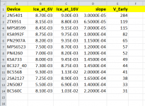
The table in Art Of Electronics includes a line item for the best PNP in my tests (2N5401) but, alas, its Early voltage is missing. AofE tabulated values for the #2 and #3 finishers (ZTX951, MPS8599) are at least near to my measured values:
ZTX951 VA: 120 (AofE) vs 119 (MJ)
MPS8599 VA: 170 (AofE) vs 115 (MJ)
AofE doesn't include the BC560 or the BC337, but it does include the somewhat similar BC860 whose Early Voltage is listed at 30, tolerably close to my BC560 measured value of 31.
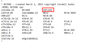
Cordell Audio's website does have a SPICE model of the BC560, showing an Early voltage of 160 volts - wow. Yet another reason not to blindly accept simulation results as 100.000% perfect predictions of physical reality. But diyAudio members are cautious skeptics so this is preaching to the choir.
_
ZTX951 VA: 120 (AofE) vs 119 (MJ)
MPS8599 VA: 170 (AofE) vs 115 (MJ)
AofE doesn't include the BC560 or the BC337, but it does include the somewhat similar BC860 whose Early Voltage is listed at 30, tolerably close to my BC560 measured value of 31.
Cordell Audio's website does have a SPICE model of the BC560, showing an Early voltage of 160 volts - wow. Yet another reason not to blindly accept simulation results as 100.000% perfect predictions of physical reality. But diyAudio members are cautious skeptics so this is preaching to the choir.
_
Attachments
Early Voltage (or the same thing the other way, Hoe) is never specified and thus poorly controlled in production.
It can relate to breakdown voltage, which implies it is a trade-off against root of hFE. However a high Vceo device can have other leakage paths which reduce EV.
There are cascade current sources which effectively multiply impedance. That can't get you where you are going?
It can relate to breakdown voltage, which implies it is a trade-off against root of hFE. However a high Vceo device can have other leakage paths which reduce EV.
There are cascade current sources which effectively multiply impedance. That can't get you where you are going?
Why not do both? Pick a high-VA transistor and then use it in a multiple transistor circuit for yet-further enhanced output impedance.
In my DIY assembly of one-of-a-kind, low volume audio components, I don't mind the extra ten minutes spent verifying that this one particular transistor I'm about to solder down, has excellent measured Early voltage. Those ten minutes don't cost any money; they are hobby minutes and are, by definition, enjoyable. Those minutes are a benefit not a cost.
Of course I will buy ten 2N5401s from every manufacturer that Digikey and Mouser and Arrow and Avnet carry, just to find out if there's significant variation from vendor to vendor (and lot to lot). And I will also buy ten BC560Cs from each mfr just to find out whether my "VA=30" result is an outlier, or a median value. Assuming the future data matches today's measurements, I am damn glad I know that 2N5401 has much better measured output conductance than BC560. It helps me decide which footprints / pinouts to put on my PCB design.
As you know, (Beta * VA) is a useful figure of merit that helps identify the very best transistors. It's so well known that Douglas Self has put it in his books. Measured values of VA have the advantage of being real, and median-of-measured-VA values have the advantage of being both real and repeatable. So I feel quite comfortable choosing devices based on median-of-measured-Beta times median-of-measured-VA, or other (proprietary) figures of merit derived from measured data but not disclosed on public websites.
Robert Pease wrote an article on transistor Mu vs Beta and pointed out that they are inversely related. Higher Beta means lower Mu. Mu can be approximated by dividing the Early voltage by the thermal voltage. Of course Mu is also 1/Hre so you can estimate the Early voltage from that transistor parameter.
please pardon my spelling.

mark:
thanks for sharing your findings.
It's very useful and your rational makes sense to me.
mlloyd1
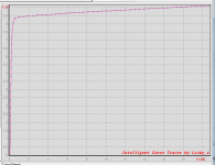
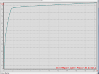
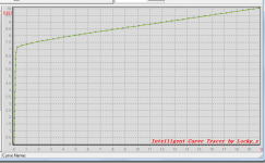
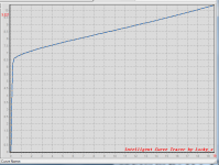
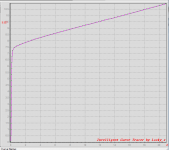
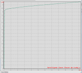
It's the "Intelligent Curve Tracer" by diyAudio member Locky-Z. There are discussion threads on this site which talk about its design philosophy; the "intelligent" feature is that he tests both NPN transistors and PNP transistors (and FETs and other devices) with hardware that uses only positive power supplies. There are no negative power supplies inside. Instead he makes "intelligent" use of (programmable) positive supplies.
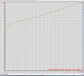
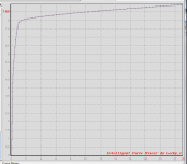
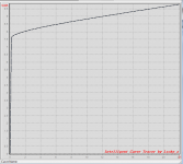
The curves in post#1 probably looked slightly unusual to your eye, since
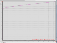
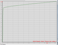
Then I grabbed Ice@6V and Ice@16V from the plot, and put those values into Excel. The spreadsheet performs a little arithmetic, and spits out the Early voltage.
The curves in post#1 probably looked slightly unusual to your eye, since
- PNP transistors are plotted in the first quadrant rather than in the third quadrant
- The Y axis scale is in milliamps not amperes
- They are Ice vs Vce plots, but at only one single value of Ibe. Not the "stepped" Ibe plots you see in datasheets.
Then I grabbed Ice@6V and Ice@16V from the plot, and put those values into Excel. The spreadsheet performs a little arithmetic, and spits out the Early voltage.
I measured four more thru-hole PNPs: 2N3906, 2N4403, MPSA92, 2SA970BL. They are indicated with light blue rows in the table below. Also I fixed a typo in the table; the correct part number for row 11 is PN4250 with a five. You can see that the MPSA92 curve exhibits a bit of quasi-saturation in the zone 0.5V < Vce < 2.0V.
_
_
Attachments
It all lines up beautifully I must say - the high-Vce, moderate-beta parts come out on top, while low-Vce, high-beta parts like BC560 and 2N5087 are the losers. As demonstrated by 2N2907A and 2N4403 vs. BC556B and 2N3906, higher-current parts also appear to fare better. (BC327 has fairly high beta for what it is, no surprise it wouldn't be that great for VA.) I wonder whether one could model all of this somehow...?
Ccb is probably going to be another kettle of fish entirely, of course. Higher Vce / lower beta are still going to be beneficial, but for obvious reasons the fatter parts are going to exhibit higher capacitance. (And then there's the whole issue of Ccb vs. Vcb.) That's what makes this whole stuff so much fun.
Ccb is probably going to be another kettle of fish entirely, of course. Higher Vce / lower beta are still going to be beneficial, but for obvious reasons the fatter parts are going to exhibit higher capacitance. (And then there's the whole issue of Ccb vs. Vcb.) That's what makes this whole stuff so much fun.
Last edited:
Thank you very much, sgrossklass and stormsonic! I will buy some more Zetex PNPs and try them out; maybe the "VAF" parameter values in Zetex's SPICE model library, will be good predictors in suggesting some promising candidates to measure.
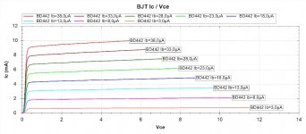
AofE 3rd Edition Table 8.1 says the TO-126 medium power NPN called BD437 has stupendously good Early voltage; I wonder if its PNP complements BD438 and BD442 are similarly excellent. Will spend time and treasure to find out. And maybe a few more TO-126 devices from ST and Toshiba.
AofE 3rd Edition Table 8.1 says the TO-126 medium power NPN called BD437 has stupendously good Early voltage; I wonder if its PNP complements BD438 and BD442 are similarly excellent. Will spend time and treasure to find out. And maybe a few more TO-126 devices from ST and Toshiba.
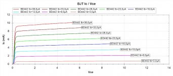
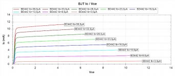
Check out the Zetex SPICE model library; there are several PNPs with "VAF" model parameter values greater than 300V, and one with VAF=1060 volts. The map is not the territory; the SPICE model is not the actual transistor; nevertheless I just ordered quite a few of the Zetex parts. And a bunch of ST and ONsemi and Fairchild devices too.
However I decided not to order the (Fairchild) KSA1142, because its complement device KSC2682 has been obsoleted and is no longer available. Boo hoo.
However I decided not to order the (Fairchild) KSA1142, because its complement device KSC2682 has been obsoleted and is no longer available. Boo hoo.
Mark Johnson said:However I decided not to order the (Fairchild) KSA1142, because its complement device KSC2682 has been obsoleted and is no longer available. Boo hoo.
2SC2682 available @ reichelt.de, made by ISC
Attachments
While waiting for my next batch of transistors to arrive, I rummaged around my parts bins and found five more PNPs to measure (highlighted in pink). I also measured Beta @ Ice=1.0mA with Vce=10V, for every transistor. The Beta measurements appear in column C. Finally I added the name of the manufacturer when known ("n/a" means I couldn't be sure), and the VCEO & Cob max specifications from the datasheets.
_
_
Attachments
- Home
- Amplifiers
- Solid State
- Measuring the Early voltage "VA" of some PNPs at 8mA