xrk971
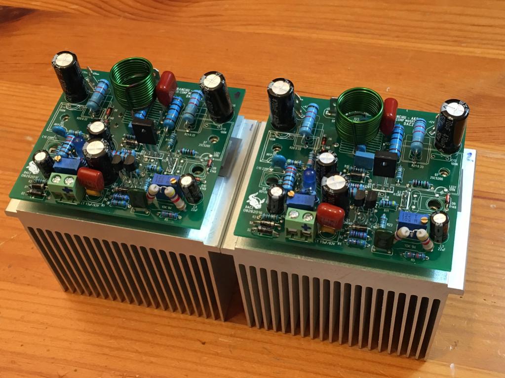
You have very nice mosfets !! They are good for drivers in a bigger project. Very hard to get them !! Lovley setup, simple and clear.
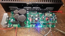
My last project (three of them at the one PCB), very happy that I didn't blowed it up. I was going to test all protections but by mistake it has testet itself
You have very nice mosfets !! They are good for drivers in a bigger project. Very hard to get them !! Lovley setup, simple and clear.
My last project (three of them at the one PCB), very happy that I didn't blowed it up. I was going to test all protections but by mistake it has testet itself
Attachments
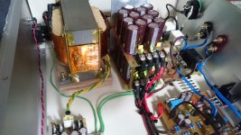
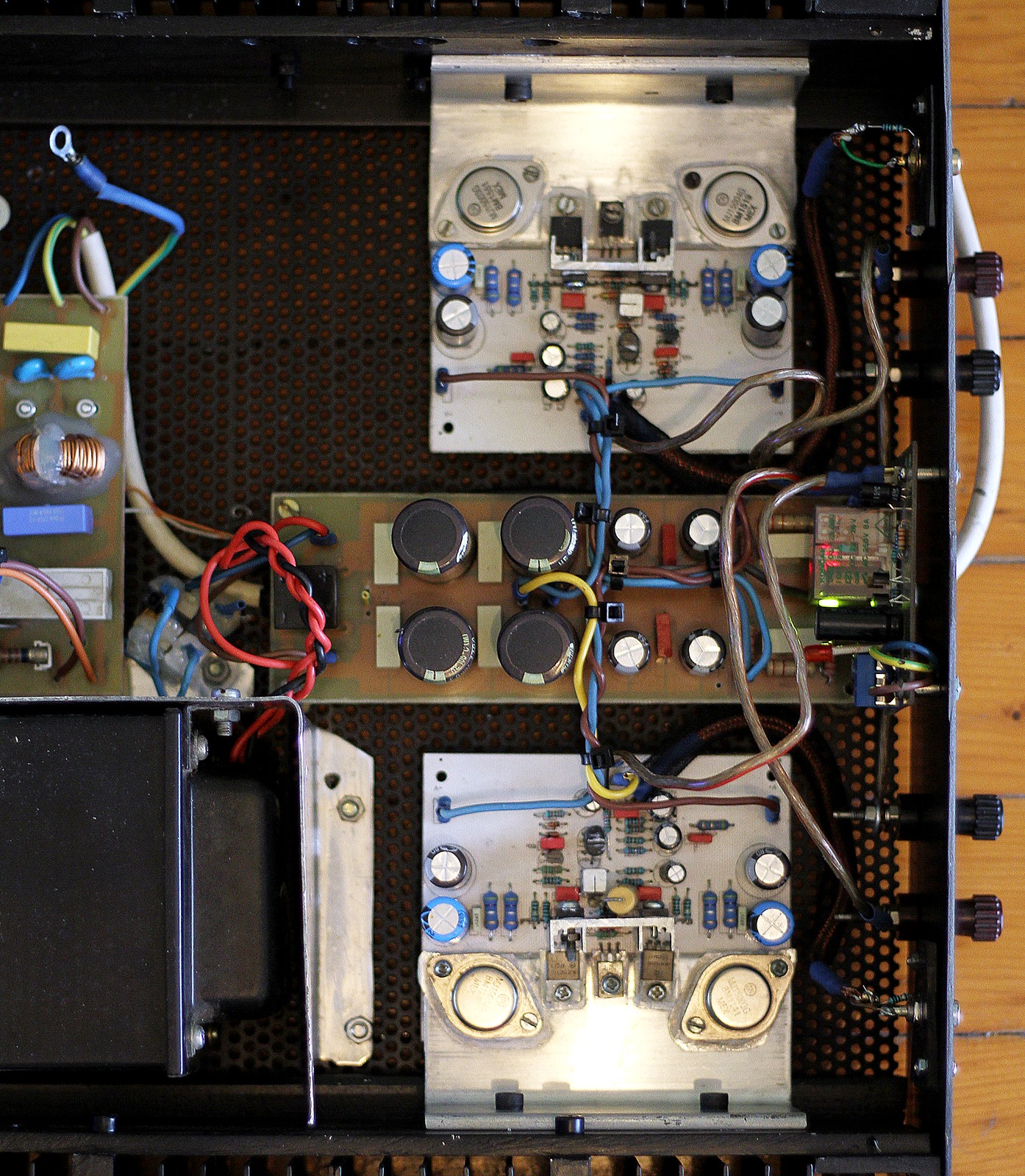
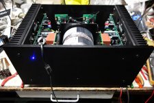
I finally found an old VHS machine to strip out and house my amplifier. This amplifier is very good, especially in terms of noise. It has very low noise, and no hum visible on a scope or audible. I like it.
That was a great idea for a cheap chassis!
xrk971
You have very nice mosfets !! They are good for drivers in a bigger project. Very hard to get them !! Lovley setup, simple and clear.
My last project (three of them at the one PCB), very happy that I didn't blowed it up. I was going to test all protections but by mistake it has testet itself
Looks like the modular (V+/PD/O/ND/V-) way has spread like wildfire here on the
forums .
NICE AMP - bet that would match or beat any OEM (or even audiophool) amp out there.
EXCELLENT layout and implementation. (A+++ professional).
OS
Looks like the modular (V+/PD/O/ND/V-) way has spread like wildfire here on the forums .
OS
Yes, because it can be cost friendly solution.
Sajti
I've been a member for a long time, but this is my first post here in diyAudio.
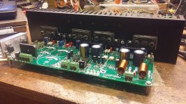
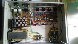
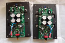
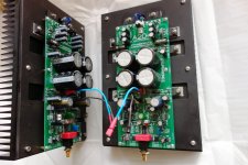
Here's the amplifier I named Decker, due to the arrangement of the PSU boards. I made it for my little boy.
Nice name, nice arrangement, nice protection, nice amp.
Also nice small heatsinks over the output transistors. But do they really do any better?
Fuses on the left board seem to be slow blow, different form the right one.
Would you share Decker's schematics?
Congrats, little boy must be laughing easily.
Thanks for the very kind words Max...
I did not do thermal measurements with this amplifier. With the 90' angled aluminum bar attached to the aluminum back-plate, it is already sufficient for normal listening levels. The supply voltage is only 50Vdc rail-to-rail at 110mA idle current. They looked good in my class-A amp, that's why I decided to just use them for this amp also.
Yes, the fuses on the Left are slow-blow, and so as in the Right.
The final fuses were 3.15A Fast-blow.
Decker is based from Rod's P3A, with some (maybe lot's) of changes.
Regards,
Leo
Attachments
OS
xrk971
Thanks for kind words, it will give me the power for the further work.
Yes V+ PD NFB ND V- is the best way, not only from money point of view but it saves a lot of time. There is no need to solder the whole amp over and over. Just a small board and off you go, it will make some fireworks or will play the music from the first go. There is a lot of fun in creation a new stuff.
Regards
Pit

OS
xrk971
Thanks for kind words, it will give me the power for the further work.
Yes V+ PD NFB ND V- is the best way, not only from money point of view but it saves a lot of time. There is no need to solder the whole amp over and over. Just a small board and off you go, it will make some fireworks or will play the music from the first go. There is a lot of fun in creation a new stuff.
Regards
Pit
After building a dozen amps I am starting to see the light.
V+ PD NFB ND V-
All the way! Next one is going daughter board / mother board... I am seeing the basic Pass F5 topology for the IPS working over and over for the last couple of class A amps I have made. A couple of JFETS and resistors/pots can do a whole lot of work.
APEX AX11
That looks real clean and nice Apex. I have't used TO-3's in a long time. They are such a pain compared to newer formats.
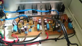
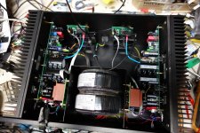
classA continue..
measure
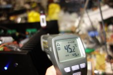
ripple at full power,photo1
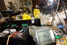
max power 25w@4Ω,photo2
square 1khz,photo3
measure
ripple at full power,photo1
max power 25w@4Ω,photo2
square 1khz,photo3
Attachments
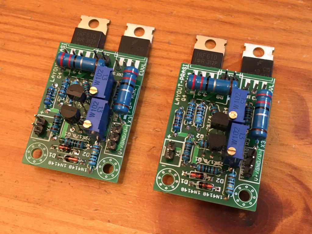
This is a F5 headphone amp by EUVL, using the abbreviated F5 topology without the Zetex's.
This layout is by Prasi and Gerbers for ordering boards here:
http://www.diyaudio.com/forums/pass-labs/271926-f5-headamp-79.html#post4840475
This layout is by Prasi and Gerbers for ordering boards here:
http://www.diyaudio.com/forums/pass-labs/271926-f5-headamp-79.html#post4840475
- Home
- Amplifiers
- Solid State
- Post your Solid State pics here