Hi,
New Member here. I am an electrical engineering student working on my senior project, a guitar amplifier. I have done a pre-amp design, and wanted to get some opinions from people who actually know what they are looking at, because this is my first attempt, and made plenty of assumptions and guesses haha. I am a long time guitar player, but have never built an amplifier before.
Here is the design.
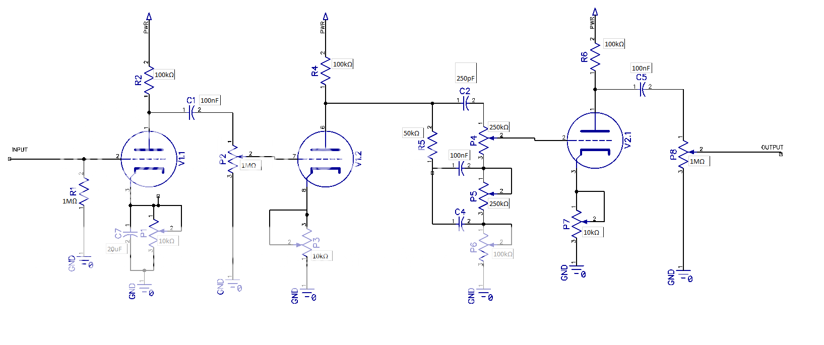
The tubes are all 12AX7, and the intended operating point is 250v B+, Plate current 1.6mA, all 10k bias adjust pots set to 1K. Eventually I will use resistors instead of pots, but I want to experiment with different operating points.
What motivated me to reach out for opinions and help was that I calculated the gain of the preamp and got roughly 107db or 250,000 v/v for the entire preamp, using the equation:
gain = u * (RL/(RI+RL)
where u is the amplification factor (100 on a 12Ax7) , RL is the plate load resistance, and RI is the internal plate resistance (taken to be 52k ohm from 12AX7 datasheet curves at my operating point). 107dB seems extreme, and I realize the tubes will saturate long before thy put out thousands of volts, but does this mean that the amplifier will almost always be very distorted, unless the gain pot is turned way down?
Going off designs I've found in books and from schematics found online, my design doesn't seem too far fetched to me. (Looked at many classic fender preamps, and many use 3 gain stages as well and get great clean tones.) I can't find a decent source online as to how much gain is in a typical guitar pre-amp either.
I realize looking this over may take some time, but if anyone had suggestions, I would really appreciate hearing them. Always willing to learn more.
Thank you in advance,
Kevin
New Member here. I am an electrical engineering student working on my senior project, a guitar amplifier. I have done a pre-amp design, and wanted to get some opinions from people who actually know what they are looking at, because this is my first attempt, and made plenty of assumptions and guesses haha. I am a long time guitar player, but have never built an amplifier before.
Here is the design.
The tubes are all 12AX7, and the intended operating point is 250v B+, Plate current 1.6mA, all 10k bias adjust pots set to 1K. Eventually I will use resistors instead of pots, but I want to experiment with different operating points.
What motivated me to reach out for opinions and help was that I calculated the gain of the preamp and got roughly 107db or 250,000 v/v for the entire preamp, using the equation:
gain = u * (RL/(RI+RL)
where u is the amplification factor (100 on a 12Ax7) , RL is the plate load resistance, and RI is the internal plate resistance (taken to be 52k ohm from 12AX7 datasheet curves at my operating point). 107dB seems extreme, and I realize the tubes will saturate long before thy put out thousands of volts, but does this mean that the amplifier will almost always be very distorted, unless the gain pot is turned way down?
Going off designs I've found in books and from schematics found online, my design doesn't seem too far fetched to me. (Looked at many classic fender preamps, and many use 3 gain stages as well and get great clean tones.) I can't find a decent source online as to how much gain is in a typical guitar pre-amp either.
I realize looking this over may take some time, but if anyone had suggestions, I would really appreciate hearing them. Always willing to learn more.
Thank you in advance,
Kevin
You have strung together three basic triode gain stages. Nothing wrong with it, nothing special or different about it.
I think if you tack this together on a bread board and experiment, with your 100k plate loads, you will probably find the 1k-2k cathode resistors you see everywhere will likely be optimal. If you are really interested, I might suggest exploring different plate resistor values. Like say 220k vs 100k. Nothing wrong with 100k, but you did say you wanted to check different operating conditions.
There is a thread about this book elsewhere on this forum, but here is the Valve Wizard web site, I suggest you go explore that. A lot of material in the book is also covered to some degree on that web page. I do recommend getting that book and reading it, I have one on my shelf. I refer to the book about designing preamps for guitar amps.
How to design valve guitar amplifiers
I also suggest looking more closely at Fender and other schematics of real amps. There is a lot of tone shaping and gain trimming in amps. The cathode bypass cap has a large affect on gain and response. You will find brightness caps across volume controls and also across interstage voltage dividers.
Watch your overall gain. The tone stack is subtractive, so it knocks signal levels down a lot of decibels. But sometimes after so many stages, the whole thing gets unwieldy. SO voltage dividing resistors are added between stages. One can add a bypass cap to the top resistor to brighten up the signal as it passes. Or across the lower resistor to roll off excess highs.
This might be out of sync with the thread. there is a delay in my posting, as I am still being moderated.
I know I have strung together classic triode gain stages - this was my first design attempt, wasn't trying to do anything fancy.
I have 220k plate resistors, and intended on trying them to get a feel for how that sounds. If anything, that should raise my gain, correct?.
Before I play around with adding brightness caps and other tone shaping stuff, I want to see what the natural frequency response of the amplifier is. The university is mandating that it be able to achieve a relatively flat frequency response over 80-1200 Hz, so my tone shaping will likely be to make the spec. Once I get that, I will try and tune it to sound "good".
I chose the fender style tone stack because it has a flat frequency response over those frequencies with the mid almost all the way up and the Bass and Treble all the way down. (Duncan tone stack calculation is a great tool).
Are my load resistors (the 1M pots) too large? I had a professor who said and I quote "I don't know anything about tube amps but I feel like the 1M load resistors are too large." I tried to get him to explain why, but he didn't know/ was talking out the side of his neck. Smaller load resistors would reduce the gain somewhat, so I guess that is something to consider.
Thanks again,
Kevin
If you want a quick fix to reduce gain then slot in a 12au7 valve.
Quite a few people don't like the 12au7 but I have found it sounds sweet.
You will need to be careful with your layout as the 12ax7 is very touchy and easily picks up hum.
Keep valves and audio circuit away from mains transformer and high AC volts.
Keep heater wires twisted and away from audio as much as you can.
If you decide to go to pcb then plenty of ground connected copper pours works well.
You will not have anywhere near 100db of gain. First off the load impedance that the tube sees is the plate resistor (100K) in parallel with the combined input impedance of the next stage.
For the first and third stages this is the 100K plate resistor in parallel with the 1 meg pot, or roughly 90K, in parallel with the input capacitance of the following stage.
Your second stage feeds the tone stack, which has a variable input impedance depending on where the pots are set.
Your gain formula only takes into account the ideal situation. The gain will be less when the cathode resistor is not bypassed.
I find that the typical (1.5 to 2.7 K cathode resistor with bypass cap, and 100 K plate load) 12AX7 stage gives a V/V gain of about 40. The tube driving the tone stack will have less gain due to the load of the tone stack. A cathode follower or mosfet buffer is often used to drive the stack with a low impedance source. This gives you a V/V gain of about 3000 with everything cranked wide open (best guess).
The typical Fender / Marshall / Vox tone stack like you have has about 20 db of loss, depending on settings and driving impedance. Use the Duncan Amps tone stack simulator to play with it.
TSC
I have tinkered with similar circuits for about 50 years. I find that a 1 meg pot will work, but you may hear some high frequency rolloff with the volume / gain set at midrange. This is due to the low pass filter created by the pots resistance and the input capacitance, which is the sum of the grid to cathode capacitance and the grid to plate capacitance times the gain of the stage (known as Miller capacitance). I prefer 250K or 500K, which will reduce gain a bit.
For experimental circuits like this, add a cathode bypass cap in series with another 10K pot to dial in the gain / tone of each stage. Your guitar, music, and playing style will dictate what works best for you. Often smaller values of bypass and coupling caps will give you a better "tone." Too much gain in the bass frequencies "muddies" up the tone, especially with cranked distorted sounds, and some speakers.
You will need to be careful with your layout as the 12ax7 is very touchy and easily picks up hum.
Keep valves and audio circuit away from mains transformer and high AC volts.
Keep heater wires twisted and away from audio as much as you can.
I have twisted heater wires, and I was thinking of rectifying the heater to DC, which I have heard of, but know is not used on the old fender amplifiers I have been looking at. I am using shielded wire wherever I can to reduce hum as well. I am in the process of assembling the amplifier right now, can't wait to see how it works!
If your task is to make a flat amp, then a guitar amps is really not your target. Guitar amps are anything but flat, and intentionally so. PA systems all sound alike, guitar amps all have a characteristic sound. You can easily tell the difference between a MArshall and a Fender.
Hum is always a factor in tube amps, but be aware there are a zillion different sources of hum, and each requires its own abatement. In other words power supply ripple and poor grounds can each cause hum, but all the power supply filter caps in the world will not help a bad ground connection, and any attempts to improve grounding will do nothing for ripple hum.
I suggest just twist your heater wires and keep them away from signal wires - especially grid wires - as much as possible, and when the heater wires and signal wires have to come together, it is best that they cross at a right angle. But for now, I'd power them with plain old 6v AC, and see what the hum level is. As I said, heater hum is only one of many hum sources. You may not have a heater hum issue, and then why waste time solving a problem you don't have?
You really do want your 6v referenced to ground. if the heater winding on the power transformer has a center tap, ground it. If not, you can easily make a "virtual ground" with a pair of 100 ohm resistors. One to each side of the 6v, then ground them. Even just connecting one side of th heaters to ground is better than no ground reference.
Really high gain amps are often powered with DC on the heaters, at least the first stage or two. But old Fenders, which this resembles, usually don't suffer much on their AC. But if you do get heater hum, before rectifying the heater power, you might try elevating the heaters. In other words, offset the 6vAC from ground by some DC voltage. An easy way is to connect the heater center tap, or the virtual tap to a positive voltage. In guitar amps that are cathode biased in the power amp, a common trick is to use the natural positive voltage at the cathodes, by connecting the center tap there.
Might be a good idea to put a small resistor in series with each bias adjusting pot to ensure that you don't accidentally set it to zero.
What is the input stage of the power amp this will be driving? See how your ouput stage will deal with the loading. With a 1 MB pot there your interconnecting cable will be susceptible to noise and hum.
What is the input stage of the power amp this will be driving? See how your ouput stage will deal with the loading. With a 1 MB pot there your interconnecting cable will be susceptible to noise and hum.
Good Idea with the resistors. I will do that. Also thanks for all the other suggestions, they are great! I really appreciate it
I was playing around with simulations today, (I realize they are just that-simulations, and the models may not behave exactly like the tube does.). What kind of gain should I be aiming for out of my preamp? I will be driving a 6V6 SE power stage, at least for now.
What max level of voltage swing does the 6V6 "want" on it's input? The way I understand this, it has to do with grid bias voltage. If my grid is biased, say -13V, if the AC amplitude of the incoming signal swings lower than -13V, it will distort. Is this correct?
So I obviously want to be able to dial in some distortion, I can do this using the "Master" volume pot, but is there a level that is too much to put into a 6V6? Can a 12AX7 put out enough voltage to damage the next stage? In simulation, I am seeing the voltage swing as low as -100v, and as high as 50V, with clipping. That seems really high to me, but I really don't know.
Here is my simulation pic, the green line is the voltage across R14 and R16, and the blue line is the voltage across R14 only. (master volume turned down, but if it was turned up, you'd get the voltage on the green line on the grid of the power amp stage.)
Here is another shot, with the "gain" pot turned down. (attenuation after the 1st gain stage)
I was playing around with simulations today, (I realize they are just that-simulations, and the models may not behave exactly like the tube does.). What kind of gain should I be aiming for out of my preamp? I will be driving a 6V6 SE power stage, at least for now.
What max level of voltage swing does the 6V6 "want" on it's input? The way I understand this, it has to do with grid bias voltage. If my grid is biased, say -13V, if the AC amplitude of the incoming signal swings lower than -13V, it will distort. Is this correct?
So I obviously want to be able to dial in some distortion, I can do this using the "Master" volume pot, but is there a level that is too much to put into a 6V6? Can a 12AX7 put out enough voltage to damage the next stage? In simulation, I am seeing the voltage swing as low as -100v, and as high as 50V, with clipping. That seems really high to me, but I really don't know.
Here is my simulation pic, the green line is the voltage across R14 and R16, and the blue line is the voltage across R14 only. (master volume turned down, but if it was turned up, you'd get the voltage on the green line on the grid of the power amp stage.)
An externally hosted image should be here but it was not working when we last tested it.
Here is another shot, with the "gain" pot turned down. (attenuation after the 1st gain stage)
An externally hosted image should be here but it was not working when we last tested it.
Last edited:
Can a 12AX7 put out enough voltage to damage the next stage
A 12AX7 is not going to blow up a 6V6 type tube, without some help from something like a mosfet buffer.
Voltage, yes, +50 volts for a long time will blow the tube. Can your circuit put enough CURRENT into the grid to fry it, No. You will never get 50 volts into the grid from your circuit.
Yes your simulation may show -100 volts (which could be real) which will totally cut off the 6V6, but not hurt it, and +50 volts, which will not be realized. The 6V6 will start to draw grid current when you try to drive it's grid positive. This will clamp the positive going drive voltage somewhere in the +10 volts region (if that) with a circuit like you show. Continued operation in this manner will cause bias shift and blocking distortion (farting out), but will not damage anything. You can take measures to prevent blocking distortion, but it is not needed for a "first time design" unless you really want to dig into it, just turn down the volume / gain a bit.
It's bad, but not quite that bad - only about 273 k, actually. There is one 500k resistor to ground, and a second 600 k resistor (the other half of the pot, plus the anode resistor R6) running to B+, which is also AC ground.When that 1M control is in mid position, the output impedance is a massive 500k.
So the Thevenin impedance is 600k in parallel with 500k, which is about 273 k.
However, I've noticed audible loss of treble in a guitar amp, as a result of using a 500k pot (not 1M) to feed less than a foot of shielded cable. So your warning is very much on point.
-Gnobuddy
Alright, I'd like to update this thread and ask a few more questions.
I constructed the amplifier and it actually works! I believe my pre amp gain is way too high, as the amp goes into distortion early with the gain pot barely turned up. I was gonna try what is suggested and switch the gain pot for a 500k or 250k.
If you continue to turn the gain pot up, there is some oscillation maybe 5-4Hz, sounds like vibrato effect. It is not a hum, but only present when playing. Would it make sense to remove one of the gain stages? I feel like this could solve the problems as there is already too much gain. How abut making a switch to 12ay7, 12at7 or 12au7?
In general, the amp sounds good at lower gain values, possibly a little muddy though. should I think about putting caps in series with the gain pot? I am going to experiment with changing the bias point on the pre amp tubes to see what that does. Right now the cathode resistor is 1.5k for all the stages and the voltage is 1.5V so current is about 1mA.
B+ is 350v for the 6v6 and 250v for the 12Ax7's
Thanks again for any advice!
Congratulations! Having grown up with semiconductors, I remember a similar sense of surprise when my first firebottle-based circuit actually worked.I constructed the amplifier and it actually works!
")
For those who grew up in the valve era, I'm sure many had exactly the opposite surprise, that a tiny speck of sand in a blob of plastic could actually do something electrically significant.
You have numerous options to lower the gain - one of the simplest is to introduce fixed voltage dividers between stages. Interstage attenuation is very much a feature of many (most?) modern valve guitar amp designs.I believe my pre amp gain is way too high, as the amp goes into distortion early with the gain pot barely turned up.
Other options include removing cathode bypass caps, or simply taking your output signal from the cathode of your final triode (rather than from it's anode). That will drastically lower the gain, if that's what you want.
This won't lower overall gain much (assuming you're feeding the output into something with a 1M or higher input impedance). It might improve the overall bandwidth, i.e., extend the treble response.I was gonna try what is suggested and switch the gain pot for a 500k or 250k.
You know the equation for closed-loop gain in a feedback amp? Well, the condition for oscillation (denominator = zero) can occur at low frequencies, if you happen to have sufficient phase shift down there.If you continue to turn the gain pot up, there is some oscillation maybe 5-4Hz, sounds like vibrato effect.
In an amp like this, with capacitor coupling everywhere, plus additional phase shifts from the power supply decoupling capacitors, it is quite possible to end up with sufficient phase shift at a low frequency to cause oscillation. It even has a name, "motorboating".
The cure is relatively simple, either lower the gain, or reduce the phase shift, at the oscillation frequency.
The surprise, to me, is that you have sufficient gain at such a low frequency (a few Hz) to cause oscillation.
I have built exactly one original-design guitar amp, so take my input with a grain of salt. But what you discovered is very typical - and the usual cure is to lower the values of coupling and/or cathode bypass capacitors, narrowing the bandwidth of the guitar amp by removing some of the low frequency response.In general, the amp sounds good at lower gain values, possibly a little muddy though.
How far you go in this direction, is quite dependent on your personal preferences, and the type of music you intend to play through this amp. Big fat jazz chords might require flat response down below 100 Hz, but little to no distortion will be used. Screaming 1970's "power chords" need very little bass response, but lots of distortion. 1990's metal? Excruciating amounts of distortion, "scooped" EQ, et cetera.
I think that 1.5k cathode resistor for 12AX7s was in the original RCA manuals, many decades ago. Leonidas lifted it from the RCA manuals, everyone else lifted it from Leo, and its still very much in evidence in tons of 12AX7 based guitar preamps.Right now the cathode resistor is 1.5k for all the stages and the voltage is 1.5V so current is about 1mA.
-Gnobuddy
Hey! Vibrato is expensive. If you can keep it tamed, you might have a good thing there. However, I think you're talking about tremolo. (Tremolo is amplitude modulation - volume/gain variations; vibrato is pitch /frequency variations).
Please check if your bias point is stable - if it is going up and down then that could be causing gain changes.
However, I think you're talking about tremolo. (Tremolo is amplitude modulation - volume/gain variations; vibrato is pitch /frequency variations). Please check if your bias point is stable - if it is going up and down then that could be causing gain changes.
Leonidas Fender, and the corporation he named after himself, both consistently failed to use those two terms correctly.(Tremolo is amplitude modulation - volume/gain variations; vibrato is pitch /frequency variations).
And what could be causing that to happen?Please check if your bias point is stable - if it is going up and down then that could be causing gain changes.
-Gnobuddy
tone stack
if someone didn't mention it, they should be driven with a cathode follower
also, that midrange control is kinda pointless, adjusting it simply raises or lowers the overall gain. A lot of guitar amps don't use the cathode follower to drive the tone stack, perhaps they feel it doesn't matter since a guitar is supposedly only good to 10 KHz
In a distorting amplifier, the signal is not symmetrical, so it causes a DC offset.And what could be causing that to happen?
Try adjusting the value of C7 (the cathode bypass for the first tube). Note: the value you need depends on the setting of the cathode resistor, so keep that in mind every time you change the gain.
- Status
- This old topic is closed. If you want to reopen this topic, contact a moderator using the "Report Post" button.
- Home
- Live Sound
- Instruments and Amps
- New Member looking for opinions on my design