I've successfully connected the I2S output of the CSRA64215 board to a DAC based on the PCM5102 and using the I2S clock signal, but the jitter on the clock line from the bluetooth module looks horrendous although I've not actually measured it.
I think this jitter could explain why the board won't perform well with a DAC that has its own accurate clock. I tried this and the noise on the audio output was very significant.
Chris
In first place, assuming that your CSR module sends 32 bits L/R words, you get 64bits, thus your bit clock is probably @64fs while your PCM5102 module requires at least 128fs. I would check this point.
Second, jitter information I something I could not find from any datasheet but I have the means to measure it when I get my modules and PCB. (although my ultimate goal is to run the CSR in slave mode from my master clock)
I will investigate further around this, thanks for the idea.
It's actually working fine with the PCM5102 module which depends on the I2S clock, it's when I use an ES9023 DAC that has its own clock when I get the noise problem. I'm wondering whether a WM8804 could be used to remove the jitter from the CSR module's output, I have this IC on order to try this out.
It would be interesting to hear more details on your master clock arrangement and how you connect it to the CSR.
I ordered a slightly different model than yours because I do my own pcb for a DAC project (spdif in/bluetooth/network player to an AKM DAC with external master clock)
CSRA64215 4 2 Stereo Bluetooth Audio Module Support Avrcp A2DP Apt x CSR8645 | eBay
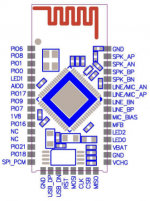
just out of curiosity for maybe another project, but which ones are the four I2S output pins from this ebay PCB? I mean BCK,LRCK,DATA and MCLCK
just out of curiosity for maybe another project, but which ones are the four I2S output pins from this ebay PCB? I mean BCK,LRCK,DATA and MCLCK
I've attached the document I got with my module which is, I believe, just a breakout board for the CSR64215 module.
I'm not sure about MCLCK, but the others are as follows:
DATA -> MISO (pin 11)
BCK -> CLK (pin 9)
LRCK -> CSB (pin 10)
Also SPI_PCM (pin 7) has to be connected to GND to enable I2S.
The PCM5102 DAC uses BCK to derive its internal clocks.
Chris
Attachments
I've attached the document I got with my module which is, I believe, just a breakout board for the CSR64215 module.
I'm not sure about MCLCK, but the others are as follows:
DATA -> MISO (pin 11)
BCK -> CLK (pin 9)
LRCK -> CSB (pin 10)
Also SPI_PCM (pin 7) has to be connected to GND to enable I2S.
The PCM5102 DAC uses BCK to derive its internal clocks.
Chris
and this is extracted from mine, the chip on the pcb is rotated by 45 deg (CSRA64215 4.2 Stereo Bluetooth Audio Module support AVRCP A2DP APT-X CSR8645)
Attachments
I will investigate further around this, thanks for the idea.
It's actually working fine with the PCM5102 module which depends on the I2S clock, it's when I use an ES9023 DAC that has its own clock when I get the noise problem. I'm wondering whether a WM8804 could be used to remove the jitter from the CSR module's output, I have this IC on order to try this out.
It would be interesting to hear more details on your master clock arrangement and how you connect it to the CSR.
I just checked the datasheet of the PCM5102 beyond page 11 of pcm5100.pdf , Without master clock, the module starts on its own PLL and locks it to a frequency which suits the bit clock (page 12).
In order to recover from jitter you would need anyhow a very good pll or external crystal.
The PCMs PPL is really good, to my experience.
Agreed, and I think that's why it works well with this module. The output using PCM5102 is acceptable, but I prefer the sound of ES9023 DACs.
The text on the pdf document I attached earlier translates (via Google) to this:
PCM510x wiring
SPI_PCM: low to enable I2S
Practice Test: ES9023 do not match,
PCM510x using the internal PLL internal clock,
Adaptive, matching the best.
I2S module is for debugging PCM510x
Note: Left
I'm not sure what the 'Adaptive' refers to, whether this refers to the PCM510x's ability to cope with a poor quality incoming clock signal.
You may plot the BT modules oscillator output against the jitter to see if a better oscillator would fix this. Can't think the CSRs clock performance is that bad.
Of course it could be just my module that is bad.
Last edited:
I'm not sure what the 'Adaptive' refers to, whether this refers to the PCM510x's ability to cope with a poor quality incoming clock signal.
Of course it could be just my module that is bad.
adaptive is the process I described earlier: in absence of master clock, the pcm510x does then synthesize its own master clock.
(if they make the PLL track the input bit clock, then by nature the pll cleans out part of the bclk high frequency jitter)
by the way, a wire/signal coupling from data (low frequency) into you bit clock can also explain the bad quality...
Guys, this is an amazing thread!
About "I now give up on the idea these modules are capable of outputting any digital stream with the firmware shipped.": I see some posts above the ONKYO WR-BT300 using the CSR8645 and supporting SPDIF:
Sound Blaster USB Page
I cannot imagine CSR built a dedicated ROM for ONKYO. So it should be possible to buy such a device and read out the PSKEYs to find out which parameters enable the digital audio output - just a suggestion.
About UART: Has ANYONE been able to get ANYTHING out of the CSR8645 or CSR64215 UART interface? Even if it is only for debug (as the data sheet says), I would like to check it out...
...I see some posts above the ONKYO WR-BT300 using the CSR8645 and supporting SPDIF:
Sound Blaster USB Page
I cannot imagine CSR built a dedicated ROM for ONKYO. So it should be possible to buy such a device and read out the PSKEYs to find out which parameters enable the digital audio output - just a suggestion.
...
Sorry, I was wrong. Just see that this device has an ADC on board. So seems they are re-digitizing the analog signal from the CSR8645. Garbage.
However, still interested in the UART - anybody had any success to communicate via this interface?
Hi, no unfortunately not. There was very little information supplied, however it looks as though the PIO pins are configured as follows:
PIO6 (pin 1) MUTE
PIO7 (pin 2) -
PIO8 (pin 3) PREV/VOL-
PIO9 (pin 4) NEXT/VOL+
PIO18 (pin 5) P.P/CALL
PIO21 (pin 6) TWS
Not sure if this helps you or not.
Chris
Hi Chris
Would you be so kind and share where you found the info about the pio´s? Do you know if this is the standar pinout that the modules comes with? Or do you have to define them? Trying to build a couple of speakers and use the TWS function, just can´t seem to find enough info on how to setup the TWS...
Cheers, Erik
Hi Erik
The PIO mapping is just in the pdf I attached to an earlier post (#164):
http://www.diyaudio.com/forums/digi...ac-apt-x-module-baseboard-17.html#post4855314
Thanks
Chris
Hi,
I have bought F-3188 module on AliExpress with CSR8645, v2.0 2013.01.29 (looks the same as Onkyo mentioned in this thread). My plan was to use it with a diy car amp. I made the amp based on TDA7581 IC and it works fine. The CSR8645 module works and sound quality is better than I had expected, but there two major issues. First of all, it makes very annoying pop sound when it is turned on (does it a few times) and when it goes into stand-by. It does not make that pop sound when the playback starts. Is there any way to fix that? It also has high background noise during playback.
F-3188 gets 3,6V from LM317 reference regulator. The amp and LM317 get 12V from a computer PSU.
I am using only R+ and L+ on the F-3188 board. I could not find if CSR8645 has differential outputs, and what is that opamp doing there.
Has anyone managed to connect CSR8645 to a dac over i2S? There is a video with going to spdif and then to I2S, but it supposed to output I2S directly according to CSR datasheet.
Any help will be appreciated.
About UART: Has ANYONE been able to get ANYTHING out of the CSR8645 or CSR64215 UART interface? Even if it is only for debug (as the data sheet says), I would like to check it out...
On the modules i use (F-3188), RX/TX are not connected to the IC.
If Hi.
Will holding down the volume buttons on this module change volume several steps, or does it only act on rising edge?
And is it possible to program max volume/gain and initial volume on startup?
Yes, it is programmed to repeat steps when holding down the buttons.
And is it possible to program max volume/gain and initial volume on startup?
Yes, via SPI programmer.
Hi,
First of all, it makes very annoying pop sound when it is turned on (does it a few times) and when it goes into stand-by. It does not make that pop sound when the playback starts. Is there any way to fix that?
I'd say these are the connection/power-up sounds configured within the module. Stand-by pop is due to disabling the output stage. This can be fixed by disabling the "low power audio codec" and something like "keep stream alive".
It also has high background noise during playback.
This is due to not using differential outputs and a bad grounding scheme.
F-3188 gets 3,6V from LM317 reference regulator. The amp and LM317 get 12V from a computer PSU.
I am using only R+ and L+ on the F-3188 board. I could not find if CSR8645 has differential outputs, and what is that opamp doing there.
Do you just got a module like a "stamp" or do you got a board with the module soldered to it? The CSR8645 has differential outputs, yes. What looks like an opamp is the eeprom.
Has anyone managed to connect CSR8645 to a dac over i2S? There is a video with going to spdif and then to I2S, but it supposed to output I2S directly according to CSR datasheet.
The video shows an CSR8675 if i remeber correct. I2S is not possible on the CSR8645 with the current firmware. Actually noone got it working or have an I2S enabled firmware for this module.
Last edited:
The video shows an CSR8675 if i remeber correct. I2S is not possible on the CSR8645 with the current firmware. Actually noone got it working or have an I2S enabled firmware for this module.
Thank you for uber fast reply. I was hoping to use a dac with I2S from CSR8645 in case audio quality is not good enough as it is. It actually sounds better than good enough for car audio and better then Alpine 92 BT I have tested, but that pop and noise need to be fixed somehow. I will try to convert to unbalanced with an opamp because when it makes that pop sound the woofer moves all the way.
I saw somebody bought a different CSR module with I2S output, I guess I will have to buy that in case I can not fix pop and noise issues.
I am using only R+ and L+ on the F-3188 board. I could not find if CSR8645 has differential outputs, and what is that opamp doing there.
Your output signal is already unbalanced (right after the opamp), so what are you trying to do?

A "ground loop breaker" might help, as is it transformer coupled.
Your output signal is already unbalanced (right after the opamp), so what are you trying to do?
You said yourself it is not an op amp. I have a "stamp" board, and what looks like an op amp is GI (or GT) 4128 B2ZLI. If I get it right, it is a voltage reference IC.
The board has balanced outputs, the seller even provided schematics for converting to unbalanced output.
The pop sound is not something preprogrammed, it plays music when turned on and then it pops a few times. I do not quite get why it pops when it goes into stand-by, I thought it is supposed to do it in way to prevent any pop sounds.
- Home
- Source & Line
- Digital Line Level
- CSR8645 Bluetooth 4.0 AAC APT-X Module / Baseboard