.I thought he just wanted to unsolder the existing 3 reg and replace it another, but better 3 pin reg.
LT3042 for positive voltage.
And what is LDO PSU for negative voltage ? Pair for LT3042 ?
.
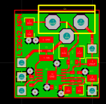
I have made a tiny layout for the npn circuit in the data sheet.
I have no idea of a negative version that does not have at least
2 op amps.
It will take some time until I can test that. A lot of stuff in the pipeline
in front of it.
regards, Gerhard
OK, I gave it a bypass. I might need it for a 3 GSPS ADC.
< https://www.flickr.com/photos/137684711@N07/29197476530/in/dateposted-public/ >
and a preliminary check of noise voltage density without a layer of shielding
and low frequency noise that may stem from the pre-amp:
< https://www.flickr.com/photos/137684711@N07/29452163806/in/album-72157662535945536/ >
For the +/- version, I have an idea wit 1 op amp in the meantime.
regards, Gerhard
My technical knowledge is pretty low level so I'd be interested in what you guys think of this:
0.8uV Ultralow noise DAC power supply regulator +-9/12/15V 1.5A*x2 - DIYINHK
0.8uV Ultralow noise DAC power supply regulator +-9/12/15V 1.5A*x2 - DIYINHK
.My technical knowledge is pretty low level so I'd be interested in what you guys think of this:
0.8uV Ultralow noise DAC power supply regulator +-9/12/15V 1.5A*x2 - DIYINHK
LT3042 for positive voltage.
And what is LDO PSU for negative voltage ? Pair for LT3042 ?
.
I think, that there is no negative pair for LT3042 ?!
.
If your negative supply comes from a separate isolated secondary and rectifier, you can use the LT3042 as a negative regulator.
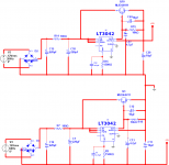
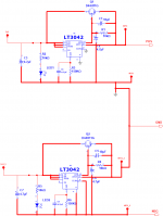
Hi, Can this work?
Dual 3042 with external NPN for higher current demand.
Attachments
That is the general idea, but the way the transistor is added looks a bit goofy to me. Do you have a source for this schematic?
Hi,
It's from LT3042 Datasheet.
BR,
Eric
Attachments
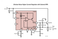
It's from LT3042 Datasheet.
same circuit as mine in post #542.
regards, Gerhard.
If you want the layout as .pdf or Gerber, just say so.
It is not a beginner's project wrt etching / soldering.
Attachments
Last edited:
same circuit as mine in post #542.
regards, Gerhard.
If you want the layout as .pdf or Gerber, just say so.
It is not a beginner's project wrt etching / soldering.
No, I don't. You're humiliating. I can make layout by myself. I post the schematic to discuss the dual 3042 for pos/neg rails.
Hi, Can this work?
Dual 3042 with external NPN for higher current demand.
Pretty sure the negative regulator will blow up. The positive-side regulator is fine, of course. But you have not properly translated the positive circuit to a negative one. On the negative regulator the ground is now positive--which is wrong. The most negative point is the -15v rail so that would need to serve as ground for negative regulator. That is my understanding. In particular, Gnd, ILM probably need to be tied to -15v. Googling "positive regulator for negative supply" or similar reveals this to be a bad idea.
Last edited:
Gerhard is just offering help. Engineers and DIYers are all lumped together on this site.
Since the schematic comes from the datasheet I see no problem with your schematic.
The negative side is NOT from the datasheet. Please look again at what was posted.
Hi,
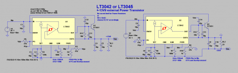
I agree with fortitudine that the Ilim and G Pins of the negstive side should be connected to the -15V line and not to gnd.
Other than that the crcuit should work.
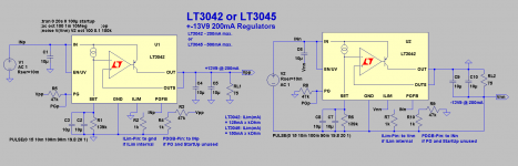
For Your notice .. there's a stronger brother of the LT3042 (200mA) the LT3045, specced with 500mA.
jauu
Calvin
I agree with fortitudine that the Ilim and G Pins of the negstive side should be connected to the -15V line and not to gnd.
Other than that the crcuit should work.
For Your notice .. there's a stronger brother of the LT3042 (200mA) the LT3045, specced with 500mA.
jauu
Calvin
Now I see it, the Ilim and G pins on the negative side should go to the negative rail.
Hi,
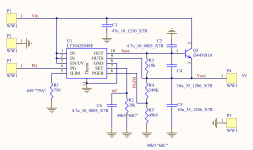
according to the above, here's the schematic. Can somebody kindly perform a LTSPICE for this? as Multisim is not supporting LT3042.
Eric
Attachments
Hi,
zip-file attached")
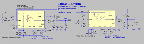
Using a external transistor one needs to either omit with the current limit feature and risk a possible damage of the power transistors in case of a failure situation, or one needs to reavaluate the ILim-Resistor values.
The sim results in +-13V9 output voltages as the setting resistors are chosen to be 139k (100+39k).
This is done as the input voltages are assumed to be 2x 15V.
A Input-Output differential of 1.1V is sufficient for the non-boosted circuit but on the edge for the boosted ... a bit more voltage differential should be beneficial.
jauu
Calvin
zip-file attached
Using a external transistor one needs to either omit with the current limit feature and risk a possible damage of the power transistors in case of a failure situation, or one needs to reavaluate the ILim-Resistor values.
The sim results in +-13V9 output voltages as the setting resistors are chosen to be 139k (100+39k).
This is done as the input voltages are assumed to be 2x 15V.
A Input-Output differential of 1.1V is sufficient for the non-boosted circuit but on the edge for the boosted ... a bit more voltage differential should be beneficial.
jauu
Calvin
Attachments
Last edited:
- Status
- This old topic is closed. If you want to reopen this topic, contact a moderator using the "Report Post" button.
- Home
- Amplifiers
- Power Supplies
- Best low noise regulator?