The good right channel has dropped to 10ma from 50ma? It has 1.2v between A & B. The left channel reads 1.1v between A & B. I took the driver board out to check things and reflowed a few solder joints,and I checked the left output module over again. The right channel jumped from 20ma to 51ma when I originaly adjusted it and it remained stable while I adjusted it back a bit to 50ma so it mustve jumped back down again,this is what its been doing for a fair while now.I connected some speakers,the right side is distorted at 10ma and the left side isnt doing anything,I cant hear a thing out of the left speaker.I crossed the channel over to the left side but didnt hear anything but I got a big shock when I mustve scratched the probe on the solder joint or something it was that loud I nearly jumped out of my skin.lol Ill check that pre-amp /power-amp switch to see if its that playing up again?
Last edited:
Quite a bit of information there......
I'm surprised the good channel distorts when the current is reduced down to 10ma but it seems that is the way it is and I was in error saying it should be OK down to very low levels (most amps are") )
)
So lets work with this......
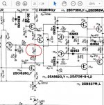
The left channel isn't reaching a sufficient voltage between A and B that I marked on the diagram to turn on the output devices. This can happen with newer semiconductors that are using different manufacturing and doping processes. The turn on voltage is slightly different and your circuit hasn't quite enough range to overcome that.
You need to be very very careful here.
If we can turn off the vbe multiplier a little more then the voltage between A and B should rise a little and bias the outputs on.
If you reduce the value of the resistor marked on the diagram by small increments then you should reach a point that allows the correct bias current to be set. I would suggest tagging resistors in parallel to this one initially. Try adding a 10k initially and if that isn't enough then remove the 10k and add an 8k2.
Always always set the trimmer to the end that gives MINIMUM current (lowest voltage between A and B) first.
(I'm also assuming that the 1.1 volts on the bad channel does actually adjust from a lower point up to this value. You might be best just confirming that to yourself before proceeding. If the bias trimmer has no effect on that 1.1 volts then there is some other problem at work. So just check that)
I'm surprised the good channel distorts when the current is reduced down to 10ma but it seems that is the way it is and I was in error saying it should be OK down to very low levels (most amps are
)So lets work with this......
The left channel isn't reaching a sufficient voltage between A and B that I marked on the diagram to turn on the output devices. This can happen with newer semiconductors that are using different manufacturing and doping processes. The turn on voltage is slightly different and your circuit hasn't quite enough range to overcome that.
You need to be very very careful here.
If we can turn off the vbe multiplier a little more then the voltage between A and B should rise a little and bias the outputs on.
If you reduce the value of the resistor marked on the diagram by small increments then you should reach a point that allows the correct bias current to be set. I would suggest tagging resistors in parallel to this one initially. Try adding a 10k initially and if that isn't enough then remove the 10k and add an 8k2.
Always always set the trimmer to the end that gives MINIMUM current (lowest voltage between A and B) first.
(I'm also assuming that the 1.1 volts on the bad channel does actually adjust from a lower point up to this value. You might be best just confirming that to yourself before proceeding. If the bias trimmer has no effect on that 1.1 volts then there is some other problem at work. So just check that)
Attachments
The left channel adjusted up to 1.4v from 1.1v with a couple of turns of the trimmer.What I think maybe happening is Ive pulled the MJ21194s out of a pro-amp that had some blown outputs in it, I threw away the blown ones and kept the rest thinking they were OK but it appears they may not be good even though they read OK on a DMM diode test? I think Ill order some new ones because Ive noticed the problem goes from one side to the other side and Im getting nowhere. The MJ21193s are new and probably arent able to bias with the old 94s?
Be logical, don't chop and change stuff yet. If there is a problem with the output then we need to prove it by measurement.
1.4 volts means there is 0.7 volts available for each NPN and PNP pair. You could just be below the threshold at which they begin to conduct.
Try what I suggested. Turn the bias back down and then add a 10k as I showed.
If you do as I suggest, and you see the 1.4 volts increase to say 1.7 volts (so 0.85 volts available per NPN/PNP pair) and still no current flows in the outputs then then and only then do we start looking for a reason why. In that situation there are only a couple of possibilities.
1/ There is a physical break between points A and B and the outputs.
2/ Both outputs in one or both of the NPN/PNP pairs are faulty. As long as one good NPN and one good PNP is there then it would work.
Be logical, don't chop and change stuff yet. If there is a problem with the output then we need to prove it by measurement.
1.4 volts means there is 0.7 volts available for each NPN and PNP pair. You could just be below the threshold at which they begin to conduct.
Try what I suggested. Turn the bias back down and then add a 10k as I showed.
If you do as I suggest, and you see the 1.4 volts increase to say 1.7 volts (so 0.85 volts available per NPN/PNP pair) and still no current flows in the outputs then then and only then do we start looking for a reason why. In that situation there are only a couple of possibilities.
2/ Both outputs in one or both of the NPN/PNP pairs are faulty. As long as one good NPN and one good PNP is there then it would work.
Re your last sentence if the system is not stable there would be a rapid increase in the current when the output stage starts to conduct.
My suggestion to cover that possibility is to have one hand on the adjustment while monitoring the voltage drop between the output pairs emitter junctions for any rapid peaking. A reverse adjustment can be quick.
Last edited:
Be logical, don't chop and change stuff yet. If there is a problem with the output then we need to prove it by measurement.
1.4 volts means there is 0.7 volts available for each NPN and PNP pair. You could just be below the threshold at which they begin to conduct.
Try what I suggested. Turn the bias back down and then add a 10k as I showed.
If you do as I suggest, and you see the 1.4 volts increase to say 1.7 volts (so 0.85 volts available per NPN/PNP pair) and still no current flows in the outputs then then and only then do we start looking for a reason why. In that situation there are only a couple of possibilities.
1/ There is a physical break between points A and B and the outputs.
2/ Both outputs in one or both of the NPN/PNP pairs are faulty. As long as one good NPN and one good PNP is there then it would work.
OK Mooly,Ill get onto it and get back on how bit went?
Re your last sentence if the system is not stable there would be a rapid increase in the current when the output stage starts to conduct.
My suggestion to cover that possibility is to have one hand on the adjustment while monitoring the voltage drop between the output pairs emitter junctions for any rapid peaking. A reverse adjustment can be quick.
Yes, you have to be careful doing this type of thing.
I would always use a bulb tester initially, and that would also give a definite indication that the preset was now working and allowing current to flow.
I keep thinking its the outputs causing the biasing problems so I installed 2 x 2SA747s and 2 x 2SC1116 on the left output module,the other side still has the MJ outputs.Should I take them out to test the left channels bias? I want to get this out of the way first because it seems more obvious to me. I havent been able to bias the amp since the MJ21193/94s were installed.
Last edited:
I personally wouldn't go swapping things at this stage. Transistors behave absolutely predictably even if there is some minor variations in characteristics. Once you reach a turn on voltage of around 0.75v (which covers any possible production spreads and manufacturing differences between old and new devices) and above for each NPN and PNP pair then they must begin to conduct. If you see sort of voltage and nothing is happening then they are faulty, simple as that.
The one thing that is bugging me a little is that for most amps, even when bias is reduced to zero, the amp still functions essentially correctly and plays normally. Having got one channel working I'm reluctant to suggest you alter or swap anything on that side.
The one thing that is bugging me a little is that for most amps, even when bias is reduced to zero, the amp still functions essentially correctly and plays normally. Having got one channel working I'm reluctant to suggest you alter or swap anything on that side.
I keep thinking its the outputs causing the biasing problems so I installed 2 x 2SA747s and 2 x 2SC1116 on the left output module,the other side still has the MJ outputs.Should I take them out to test the left channels bias? I want to get this out of the way first because it seems more obvious to me. I havent been able to bias the amp since the MJ21193/94s were installed.
The voltage amplifier stage is connected to the output transistor bases by 8R2 carbon film resistors of low wattage.
This is by design so the resistors will fuse if excess current is passed through them. I know from experience it is possible for that to happen without any visible signs to indicate failure.
You replaced some driver transistors as well as the outputs. Did you check the resistors at the time and are these still intact? It would be worth checking all the emitter resistors of the drivers and outputs as well.
Mooly made the point of checking continuity. It is important to do that by measurement. Carbon film resistors can also go high in value if they are subjected to too much heat.
Last edited:
The 8R2 resistors in question here are labelled in the Service Manual as FR meaning fusing resistor. It is less a question of what material these are made but are they intact.
I looked up the datasheets for 2SA747A and 2SC1116 - they do not have such a high cut off frequency as others with SA and SC designations.
In this regard the Gratis 2SB645 and 2SD665 I offered are comparable while being superior in power rating and voltage and current handling capacity - 150 W, 200 V, 15 A.
The MJ's may be OK if the specifications err on the conservative side of things.
Last edited:
I think I may be onto the problem? When I move the wires from the molex connectors from the driver board to the output module the milli-amps jump around when reading the bias on my DMM.Ive tried to tighten them up by taking them out and bending them out to grip the driver board pins better but it doesnt appear to be working as good as I had hoped.They must have metal fatigue? I have a steady 50ma on the right channel.Hopefully, lol. The right bias trimmer reads 380 ohms when set at 50ma. I set the left trimmer at 380 ohms and get 10ma. If I move certain wire it will go to 24ma,etc. So Ill connect them up with some spade connectors for the time being to see if I can get this amp working properly. What do you think Mooly?
I think I may be onto the problem? When I move the wires from the molex connectors from the driver board to the output module the milli-amps jump around when reading the bias on my DMM.Ive tried to tighten them up by taking them out and bending them out to grip the driver board pins better but it doesnt appear to be working as good as I had hoped.They must have metal fatigue? I have a steady 50ma on the right channel.Hopefully, lol. The right bias trimmer reads 380 ohms when set at 50ma. I set the left trimmer at 380 ohms and get 10ma. If I move certain wire it will go to 24ma,etc. So Ill connect them up with some spade connectors for the time being to see if I can get this amp working properly. What do you think Mooly?
That will have to wait until sunrise on the other side of the planet tomorrow. In the meantime here is what I think -
If this current increase is while you are touching/reorienting the wire you are adding some temporary parasitic capacitance into the circuit.
One of these wires - possibly this particular one - will be connected to the negative feedback path to the inverting signal input. The change would be seen as a signal input for the short duration.
If you buy a batch of transistors you will have to go through many to get a close match of the Vbe. This is unnecessary when the voltage multiplier reference voltage can be set with a trimpot. It is not a matter of matching the track resistance.
Measurements are still important. Service Manuals show the typical voltage levels on circuit diagrams at various points to serve as a guide for repair work.
To make use of this one I suggest you print it off, take measurements from your problem channel and note them alongside those given by the manufacturer. There is a section for each channel - record both using a different colour pen for each.
You will then be able to make a three way comparison to help you identify areas where the discrepancies lie in your problem channel and report all of these in a summary.
What do you think Mooly?
This 'moving wires around' and seeing things alter has been a constant theme as I recall
As mjona suggests, you could also be seeing parasitic oscillation as you move and touch wires which would upset DC conditions. I'm tempted to suggest something for you to try, which would both prove something to me (and also you).
The good channel. If you apply a short across the vbe multiplier (TR09/TR10) you force the bias current to zero.
It would be informative to know if the good channel still basically sounded OK in that state. If it did, then that would confirm that there is something other than just a low bias condition going on with the bad channel.
Ill do that with the TR09 but here are the readings on the base to the outputs.Most of them werent working as in no continuity from the driver board through the molex connector I have them going now except for pin 16 it reads 1.055v on the driver board and .535mv on the output base? Ill give it a good clean again and see what happens? Im taking it easy so as not to blow anymore outputs. Ive put the MJ221193/94s back in,at least Ive got that doubt about them out of the way.This 'moving wires around' and seeing things alter has been a constant theme as I recall
I'm tempted to suggest something for you to try, which would both prove something to me (and also you).
The good channel. If you apply a short across the vbe multiplier (TR09/TR10) you force the bias current to zero.
It would be informative to know if the good channel still basically sounded OK in that state. If it did, then that would confirm that there is something other than just a low bias condition going on with the bad channel.
P.S. The right channel sounds pretty good now but theres nothing on the other side.Ill do TR09 and get straight back.
Last edited:
Ill do that with the TR09 but here are the readings on the base to the outputs.Most of them werent working as in no continuity from the driver board through the molex connector I have them going now except for pin 16 it reads 1.055v on the driver board and .535mv on the output base? Ill give it a good clean again and see what happens? Im taking it easy so as not to blow anymore outputs. Ive put the MJ221193/94s back in,at least Ive got that doubt about them out of the way.
I downloaded my circuit from Hi-Fi Engine it is an 11000A is this the same version as yours - in this pin 16 is the positive supply rail sitting at 48 volts.
You say there is 1.055V at that connection point. Can you check what you have on your board.
I downloaded my circuit from Hi-Fi Engine it is an 11000A is this the same version as yours - in this pin 16 is the positive supply rail sitting at 48 volts.
You say there is 1.055V at that connection point. Can you check what you have on your board.
Nope,its the AU-11000.The SM is on Digital Docs for download on this site.
Its Alive! Its Alive! I gave the balance pot a squirt of DeOxit and the left channel sprung into life.It sounds pretty good on the little test speakers. Ill check to see if I can bias it? I forgot to upload these readings They look all wrong but the amp is playing now like theres nothing wrong with it?
Attachments
Last edited:
The right side sounds good with or without the short on TR09. Oh well Ill keep looking.
I thought it might
Low or even no bias doesn't remove the audio, it just increases the distortion.Its Alive! Its Alive! I gave the balance pot a squirt of DeOxit and the left channel sprung into life.It sounds pretty good on the little test speakers. Ill check to see if I can bias it?
Ah, now then grasshopper. Remember this
1/ Confirm that the signal reaching TR01 and TR02 base are nominally similar. That's a basic test, proving that the faulty channel is actually receiving a known good signal.
At least its getting there. If you still have a genuine low bias issue on this channel then its probably because of the differing characteristics of old vs new semiconductors... you know what to do
- Status
- This old topic is closed. If you want to reopen this topic, contact a moderator using the "Report Post" button.
- Home
- Amplifiers
- Solid State
- 47 volts on output resistors?