I can hardly get a word in edgewise! '-) But that is not my complaint. Let's keep it without hi tech overlording over the usual technically trained folks. We all have specialties, but that doesn't mean that we should 'snow' everyone else with our very specific elevated knowledge just to impress everyone else here.
Look, I took a night class at Ampex on control theory in 1968, and I made my first phased locked servo that drove the capstan of the Ampex 440 tape recorders for a number of years. I did my first velocity servo in 1969 for a cassette loaded video recorder. So go for it Pano! I hope to learn a thing or two.
Yes sir I agree. But most turntables are pivoted and they would benefit if it works. (I mean if it is worth doing and lowers distortion). Another thought is cutting a vinyl master with pivoted cutting lathe.The folks with linear arms might be upset.
Regards.
Pretty much all this has been done many decades ago when it came to pre-distortion of vinyl records. It didn't work out very well. The biggest potential headache for vinyl recording is the digital prevue which really compromises any analog tape that might be the master. Analog prevue tape heads are not that difficult for serious lathe recordists to use. However, a virtually 'perfect' preview delay could possibly be made with today's technology, perhaps 500KHz clock and 24 bits.
yes, I use that design I did for Monster distribution years ago... model something -7000. However, that is mostly a system for isolation from each piece of equipment plugged into ac power. Two Triple shielded isolation transformers driving individual isolation filters on each outlet. Most of our noise comes from within the home and from our connected equipment -- Audio-Video-Computer/ etc. So each gets filtered and isolated from one another.
THx-RNMarsh
Richard,
I have explained elsewhere that I like to put mains filters in reverse (!) on equipment that generates a lot of mains junk like not-so-clean SMPSs.
Mains filters are asymmetrical normally and set up to block junk coming from the mains (or from other equipment, through the mains). But if you can block junk from going into the mains in the first place, your whole installation benefits.
Comments?
Jan
We all have specialties, but that doesn't mean that we should 'snow' everyone else with our very specific elevated knowledge just to impress everyone else here.
It is an attribution on your part that someone has an intent to "snow," and that the purpose of their comments is to impress. You can't really know what is going on inside someone else's head.
It has been said that you have to understand something better than ever in order to teach it. Sometimes people want to help other people get things right, but struggle with how to make something that is complex sound easy to understand. Some people are better than others when it comes to that. If it doesn't come easy for someone, that doesn't mean you should infer some bad intent.
There is no simple solution or universally optimal filter for all noise situation in mains supply.Comments?
Jan
Pretty darn close.
Outer path much longer... i did that experiment on my own with low current/voltage strip line modifications for a proof of concept. it worked very well.
I was exploring the thought that on very thin pcb copper and wide enough trace, the Hf would travel on the left and right edge rather than down the middle or evenly distributed.
THx-RNMarsh
Wouldn't there also be a concentration of current density towards the return path as well as the corners edges... which I presume is because they are the points furthest away from the magnetic centre of the conductor...
A slide about half way through this shows the flat rectangular current densities nicely...
http://quickfield.com/seminar/proximity_webinar.pdf
Figure 4 of this paper shows the proximity effect, I would like to as JN if this model is simplistic as the stuff I have been looking at in more detail (as above) shows densities greater at the corners edges (again furthest away from magnetic centre has the highest current density).
http://www.ultracad.com/articles/skin effect.pdf
Richard,
I have explained elsewhere that I like to put mains filters in reverse (!) on equipment that generates a lot of mains junk like not-so-clean SMPSs.
Mains filters are asymmetrical normally and set up to block junk coming from the mains (or from other equipment, through the mains). But if you can block junk from going into the mains in the first place, your whole installation benefits.
Comments?
Jan
Also how are you reversing them? Schematic?
In general I agree that it's best to have individual filters for your equipment. The transformers (small ones) in a lot of your stuff, or SMPS, are sources of noise that can pollute the whole stereo.
Too much pressure!!!
My example fits single driver systems the best of course.
A 3 way (ahem, a 3 way speaker) will test as driver impedance give or take at every single frequency, as in an impedance sweep test. When two frequencies are involved, the amp will see a more complex load, drivers paralleled. Three frequencies, all in parallel. So for a three way 8 ohm nominal, there will be instances where the V to I ratio is consistent with 8/3 ohms. A zip cord at 100 to 150 ohms driving that? How in the world to even model such a complex system of stimulus dependent settling times, never mind one getting close to the amp I/V limits dynamically. I laugh at the impedance sweeps presented, as if that's what music actuall does to the amp..
At least bi/triamping removes some part of the complexity, granted it raises others
OK that was part one of my dumb question .Parts two and three I am still mulling and thinking maybe Bruno was right with the kii3. I have read somewhere he uses current drive for the bass units which 'might' drop out from this line of thinking. But easy to fall into the rabbit hole of lower DF gives better bass response and miss the point.
Richard,
I have explained elsewhere that I like to put mains filters in reverse (!) on equipment that generates a lot of mains junk like not-so-clean SMPSs.
Mains filters are asymmetrical normally and set up to block junk coming from the mains (or from other equipment, through the mains). But if you can block junk from going into the mains in the first place, your whole installation benefits.
Comments?
Jan
are they commercial filters or something you designed yourself? commercial filters do not filter into audio freq range.... HF-RF only.
You need to get down into audio freq range to make a difference.
You also need to know what type of noise you are putting onto the ac line. Is it CM or DM?
THx-RNMarsh
Wouldn't there also be a concentration of current density towards the return path as well as the corners edges... which I presume is because they are the points furthest away from the magnetic centre of the conductor...
[/url]
We have an infinate ground plane under it.
Corners and edges... yes..
-RNM
Wouldn't there also be a concentration of current density towards the return path as well as the corners edges... which I presume is because they are the points furthest away from the magnetic centre of the conductor...
A slide about half way through this shows the flat rectangular current densities nicely...
http://quickfield.com/seminar/proximity_webinar.pdf
Figure 4 of this paper shows the proximity effect, I would like to as JN if this model is simplistic as the stuff I have been looking at in more detail (as above) shows densities greater at the corners edges (again furthest away from magnetic centre has the highest current density).
http://www.ultracad.com/articles/skin effect.pdf
Nice articles... especially the first one with Quickfield. Thank you... worth a study esp for the field and current densities.
THx-RNMarsh
Ah, I'm not speaking about sine stimulus.
John
If you had read Moore all the way to page 242:
ITD thresholds for sinuses or band limited noise (continous stream of transients) are very comparable, 11 and 9 uSec. For single clicks, it is 28 uSec, for a stream of clicks 10 uSec.
1.5 uSec? Blind table tennis players with otherwise fortunate mutations after many years of training, who knows.
What really frosts me is amplitude only panning. Amplitude only location discrimination does not exist in nature. So from the very jump, we are asking our ear/brain combo to interpret something it is not designed to.
Then we top it off with lack of control of the signals across the entire band at ITD levels? Sheesh.
Good think I only listen to the music for the music. I'd be pretty dismayed if I were trying to reconstruct an entire soundfield accurately such that the speakers disappear...
Oh wait, isn't that the goal??
Cheers, John
Maybe there's a justification for "peeking" here... From my own work in electroacoustics years back it's clear that reconstructing, or modifying, a soundfield relies to some extent on the willing co-operation of the user. Ie, if you see the kit you believe in, and want to hear the soundfield as accurately reproduced, you will hear that... And if you enjoy that, great!
Meanwhile some of us will insist on digging around with hard facts... I enjoy just listening, sometimes over awful systems, and at the same time trying for complete understanding of what's going on! This thread has added some useful things to that understanding...
What really frosts me is amplitude only panning. Amplitude only location discrimination does not exist in nature. So from the very jump, we are asking our ear/brain combo to interpret something it is not designed to.
Time for the great thaw to set in.

Blumlein showed that intensity panning, in this drawing full amplitude to speaker A and half amplitude to speaker B, will lead to the creation of a phantom image of which both amplitude and phase add up correctly at the ears of the listener. That is why imo he became known as the inventor of stereo; he was the first to prove this mathematically .
It is good to refresh your trig to calculate the phase shift at the listeners ears (if you are so inclined) for a single case. Blumlein wrote the derivation out and I remember having studied it when all such info came to us in paper form. Must be on the internet somewhere. Can´t find a link but would be thankful if someone would post one.
Coming together nicely!
Jan
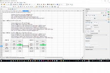
Another milestone in the development of the autoranger!
Finalised and tested the cal procedure.
Especially calibrating the freq response for 0.1dB flatness out to 100kHz is a challenge if you don't have a fully equipped lab

I now have a procedure that needs only an AC DMM with reasonable performance and a signal generator that can output 10kHz and 100kHz, preferably up to 10V or more but that's not critical.
The procedure directs you to do some measurements and enter values in a small spreadsheet and the spreadsheet then tells you what to adjust (cap trimmer) for which DMM indication.
For -20dB and -40dB settting, in both SE and BAL mode.
It's done faster than described!
Jan
Attachments
Last edited:
So then how do you think I feel when you and Scott et al start talking noise equations and folded cascades?I can hardly get a word in edgewise! '-) But that is not my complaint. Let's keep it without hi tech overlording over the usual technically trained folks. We all have specialties, but that doesn't mean that we should 'snow' everyone else with our very specific elevated knowledge just to impress everyone else here.
Personally, I prefer reading thinks I don't know, and try my best to express what I do.
Well darn, John. I was just going to talk about learning to deal with settling time in motion controlled stage scenery. Something that gave me fits designing control systems.
But I won't get too hi tech, and snow anyone with that.
He hee!!
Which is why I questioned you on that 725 hz and 1380 uSec thing.If you had read Moore all the way to page 242:
ITD thresholds for sinuses or band limited noise (continous stream of transients) are very comparable, 11 and 9 uSec. For single clicks, it is 28 uSec, for a stream of clicks 10 uSec.
1.5 uSec? Blind table tennis players with otherwise fortunate mutations after many years of training, who knows.
I am confident the 1.5 is a result of training.
John
- Status
- Not open for further replies.
- Home
- Member Areas
- The Lounge
- John Curl's Blowtorch preamplifier part II