Why not take out the existing power supply (you've already done that), put it in a separate box, and extend the four-wire power cable?
Surely that's easier than coming up with an entirely new power supply?
-Gnobuddy
Hi ! thanks for the advice and i would like to do that actually, but i cannot find a suitable extension cable.
I know for sure that this would work. The stock ps is ok per se.
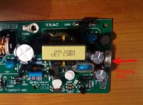
However it seems that the unit works with 12VDC. The 4 pin connector coming out from the ps has the pins connected 2 by 2.
So a single output 12V power supply should work fine.
Placing a dc socket on the rear panel would allow to try any ps around, linear or switching.
Actually this is the common solution i see for this kind of interfaces.
And now i understand why.
Thanks again, gino
are you sure you know how to buy a good one or even measure it?
consider this https://www.youtube.com/watch?v=BFLZm4LbzQU
Hi ! thanks for the kind reply.
You have centered the problem. The selection of the right one

I am in a mess.
Aside of buying a lab grade high cost one, the ones normally found around have no specifications.
I understand that a 12V smps can have ripple of the order of 100-200 mV
I would like something close to the mV.
For the measurements i would measure them not directly.
I am measuring the noise of the interface powered by the power supply.
I have some cheap others and i have measured them on the same pc with Arta software.
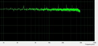
While the noise floor is a little higher no one shows similar 20-30dB spikes in noise. No one.
The noise floor is quite flat (like a floor must be
).And all have external power adapters
However this experience is very educational. Very.
Do you have maybe any advice for a decent 12V/3-5A power solution ?
Thanks a lot again, gino
I think you have to solve this problem first - even if you get a new power supply, how are you going to connect it to your TEAC interface unit? You still need a cable to run from the new power supply to the appropriate connector inside the TEAC, no?Hi ! thanks for the advice and i would like to do that actually, but i cannot find a suitable extension cable.
I know I have seen those connectors on a lot of equipment, and I think they are a type of Molex connector, but I don't know the exact model. But this forum is full of experienced engineers who will recognize it instantly - why not post a close-up photo of the connectors (both the pin header, and the cable end) in a new thread, titled "Help identify this connector?" or something like that?
One useful thing you can do is measure the spacing between the adjacent pins on that power supply PCB (making *sure* it has been unplugged from the mains for an hour first!) There is more than one pin spacing standard. The most common here in the USA is 0.1 inch (which is 2.54 mm). Unfortunately there is also a very similar metric standard (exactly 2 mm). And there are plenty of other standards too, both smaller and larger.
Knowing that pin spacing (called pitch) will help to identify the connector you need. Probably the best way is to measure the spacing between the end pins on that 4-pin connector. Divide that distance by three (there are three spaces between four pins!), and you have the pitch. Make sure to put that information in the new thread when you ask for help identifying the connector.
If you can't find a replacement cable, you can just extend the cable you already have. Cut it in the middle, and solder in four new wires to extend the length, making sure to use heat-shrink to insulate the joints. Voila, you have a new extended cable!
This assumes you have good soldering skills - if you don't, either find someone to do it for you, or learn to solder on something else first!
I can only see three pins on the power supply PCB connector, with the fourth pin missing? (See attached photo)The 4 pin connector coming out from the ps has the pins connected 2 by 2.
-Gnobuddy
Attachments
I think you have to solve this problem first - even if you get a new power supply, how are you going to connect it to your TEAC interface unit?
You still need a cable to run from the new power supply to the appropriate connector inside the TEAC, no?
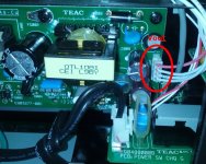
Hi and thanks again for the useful reply. I am attaching a picture with the detail of the 4 pins cable, only output from the ps. Two pins are ground and 2 the same +Vout (it should be 12VDC).
The idea is to strip them and connect 2 by 2 of course.
I know I have seen those connectors on a lot of equipment, and I think they are a type of Molex connector, but I don't know the exact model. But this forum is full of experienced engineers who will recognize it instantly - why not post a close-up photo of the connectors (both the pin header, and the cable end) in a new thread, titled "Help identify this connector?" or something like that?
Thanks a lot for the advice. I will do this weekend for sure.
One useful thing you can do is measure the spacing between the adjacent pins on that power supply PCB (making *sure* it has been unplugged from the mains for an hour first!) There is more than one pin spacing standard. The most common here in the USA is 0.1 inch (which is 2.54 mm). Unfortunately there is also a very similar metric standard (exactly 2 mm).
And there are plenty of other standards too, both smaller and larger.
Knowing that pin spacing (called pitch) will help to identify the connector you need. Probably the best way is to measure the spacing between the end pins on that 4-pin connector. Divide that distance by three (there are three spaces between four pins!), and you have the pitch.
Make sure to put that information in the new thread when you ask for help identifying the connector
i will try. I have tried to move the wires internally with the unit working to see if the noise was changing. No change.
However i have to try another thing. To disconnect some of the signal cables running close to the smps across the unit and see if the noise spikes go away.
If you can't find a replacement cable, you can just extend the cable you already have.
Cut it in the middle, and solder in four new wires to extend the length, making sure to use heat-shrink to insulate the joints.
Voila, you have a new extended cable!
This assumes you have good soldering skills - if you don't, either find someone to do it for you, or learn to solder on something else first !
I can only see three pins on the power supply PCB connector, with the fourth pin missing? (See attached photo) - Gnobuddy
No. There is an issue with the quality of that picture. It is confirmed the pins are 4.
I have attached a better picture showing the ps out cable.
2 pins are connected to ground and the other 2 also together (i guess they are +Vout )
I did not measure Vout but it should be around 12V, a very common value for this kind of unit.
This interface has a high potential for good sound.
Great converters and good mic preamps.
Thanks a lot again.
Kind regards, gino
Attachments
Last edited:
Yes, four wires in the cable. But how many pins in the power supply PCB, if you remove the cable? It looked like only 3 pins, in your earlier photo.I am attaching a picture with the detail of the 4 pins cable, only output from the ps.
Either way, you can cut your existing four-wire cable, and simply solder in four equal lengths of new wire, to extend the cable. Insulate the solder joints with heat-shrink. It won't be as pretty as a factory-made cable, but will work just as well.
Let's be honest one more time, nothing that you do with the power supply will make the interface sound better - because there is no problem with power supply noise now! There's only a picture (noise spectrum) that bothers you, there's nothing that is actually real in terms of having any effect on the sound.This interface has a high potential for good sound.
Great converters and good mic preamps.
So, it IS an excellent interface right now. Not just a potentially excellent one!
The important part is to go make some excellent music with it, now! (I'm guessing you're a musician?)
-Gnobuddy
Snegletape will work like the 3m stuff and is a lot cheaper
And these are cheap and can work wonders sometimes
regards
james
And these are cheap and can work wonders sometimes
regards
james
Yes, four wires in the cable. But how many pins in the power supply PCB, if you remove the cable? It looked like only 3 pins, in your earlier photo.
Hi ! 4 also on the pcb. I will extract it again in the weekend and try to take some serious picture ... macro
Either way, you can cut your existing four-wire cable, and simply solder in four equal lengths of new wire, to extend the cable. Insulate the solder joints with heat-shrink. It won't be as pretty as a factory-made cable, but will work just as well.
I tell you what i am going to use. These connectors here ...

then i will use a 12V adapter and see.
I am willing to bet that those spikes will vanish.
I will do it in the weekend.
Let's be honest one more time, nothing that you do with the power supply will make the interface sound better - because there is no problem with power supply noise now! There's only a picture (noise spectrum) that bothers you, there's nothing that is actually real in terms of having any effect on the sound.
So, it IS an excellent interface right now. Not just a potentially excellent one!
The important part is to go make some excellent music with it, now! (I'm guessing you're a musician?)
-Gnobuddy
Unfortunately not. I am not gifted.
I am an administrative clerk because i need a salary.
My dream would have been to work as a sound engineer. A recording engineer.
There is something magic in recording sounds and music that fascinates me.
And i would say live recordings more than studio recordings.
But where i live it is very difficult to get a life with this.
What a pity.
Thanks a lot again.
gino
Snegletape will work like the 3m stuff and is a lot cheaper ...
And these are cheap and can work wonders sometimes ...
regards
james
Hi James ! thanks a lot for the kind and helpful advice.
I have just given up at the idea of keeping the smps internal.
Better. I am about to test an external one.
If nothing will change i will have to live with those spikes.
If instead it will work i will place a dc socket on the rear panel and done.
Thanks again.
gino
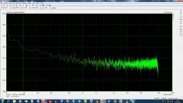
Those spikes are way down... Add a ferrite bead common mode over the cables will probably lower the levels even more... But from the last shot they looked to be 116dB down!!!!
Connectors try these though a pin pitch would help...
Micro-Fit 3.0? Connectors - Molex
Connectors try these though a pin pitch would help...
Micro-Fit 3.0? Connectors - Molex
Those spikes are way down... Add a ferrite bead common mode over the cables will probably lower the levels even more...
But from the last shot they looked to be 116dB down !!!!
Hi and thanks a lot for the valuable advice.
Problem is that this is the only one with spikes ... and i have tried now at least 5 ! they have all a flat noise floor ranging from -100 to -125dB (mic in, zero gain).
Connectors try these though a pin pitch would help...
Micro-Fit 3.0? Connectors - Molex
as a 1st try i will do something temporary. Because clearly if the spikes persist even with an external ps i will live with that of course.
This would mean that there is something more serious going on.
From what i have gathered, i am pretty confident they will go away and leave a -140dB noise floor ..
At that point i could search for a very good 12VDC power supply solution.
I will let you know the outcome.
Thanks again, gino
P.S. because i have also another doubt.
I understand that these units take the 12VDC input and then they generate the needed voltage with dc to dc converters to feed all the components.
So there is a noise difficult to eliminate.
The idea is to try not adding other with the 12VDC supply.
Last edited:
Those spikes are way down... Add a ferrite bead common mode over the cables will probably lower the levels even more...
Hi ! yes ! i have bought some ferrite cores to snap around the dc out 4 wires cable. I am very curious to see. I have bought 20
I have a question.
If i snap around the dc cable more the one will the effect be stronger ?
like putting 3 or 4 around the dc cable out of the smps.
I am very very curious. For sure a test to do.
Thanks a lot indeed for the very valuable advice.
gino
I prefer to use LLC SMPS.
While it still switches square waves the LLC turns that into sine waves into the transformer.
This results in much less noise radiation
Hi ! thanks a lot for the very valuable advice.
Mine is mostly a curiosity.
I read from another interface i have the following:
12VDC/1.5A power supply internally conditioned to provide +48VDC and +/- 15VDC and low voltage rails for digital converters ...
My question is quite trivial.
How much the quality of the 12VDC/1.5A Adapter can influence noise and distortion performance of the unit.
10dB ? 20 dB ? nothing at all ?
difficult to say without measuring.
So i got another good interface with a 12VDC socket and i am measuring noise with any 12VDC adapter i have at hand.
Result for now ... not significant differences between cheap smps adapters.
I have some very low leve spikes here and there.
I have bought but not yet received ferrite beads to snap aroung the dc cables.
The last try could be a very low ripple linear power supply.
Like one with the ripple in the region of uV
If this one will give same result as a 5 USD smps adapter it will be anyway interesting.
I could save time and money on the adapters and look maybe for a better interface.
If i will find anything of interesting i will report.
Thanks a lot again, gino
Last edited:
Hi !
this is another usb interface with a socket for a 12VDC external supply.
just to say that even after changing the stock smps for a decent linear power supply (nothing high end) i still get some 10-20 dB spikes standing out against the noise floor.
Substantially no differences to speak of
And in this new case the power supplies are completely outside the box with the circuit.
So they must be generated internally the interface.
Like a signature of the unit.
I have still one last try to do and then i will live with that.
If i would be the designer i would try to achieve a nice flat noise floor with all my forces.
Regards, gino
Attachments
Last edited:
In post #50 you said:...even after changing the stock smps for a decent linear power supply (nothing high end) i still get some 10-20 dB spikes standing out against the noise floor.
<snip>
So they must be generated internally the interface.
<snip>
[special="I understand that these units take the 12VDC input and then they generate the needed voltage with dc to dc converters to feed all the components."]%[/special]
If that is correct, there are other switching power supply stages inside the TEAC box - the DC-to-DC converters you mention are themselves switching supplies.
That would explain why there continues to be switching noise spikes in your noise floor measurements.
But, once again: the spikes that have been worrying you so much are incredibly weak, at -120 dB or lower, and they are at such a high frequency that not even bats could hear them. They are completely unimportant, will have zero effect on your recordings, and all the time and energy you are spending on them is a complete waste of your precious resources. It's like finding a tiny spot on your skin, and insisting you have cancer, even though a hundred doctors tell you no, no, no, you are perfectly fine, just go have fun.
There's an old English saying "a wild goose chase". It means, and I quote from a dictionary, "a foolish and hopeless pursuit of something unattainable". Ginetto, my friend, this is a wild goose chase!
You must have bought this interface to make some recordings - why not put your creative energy into that? That's the place where your thoughts and feelings can make a real difference! And, you can enjoy the process and have fun, too.
I hope I haven't offended you, that was not my intention, and if I did, I apologize. I just hate to see you upset and agonizing over this, for days on end. Life is short, and you will never get back the many hours you spent measuring noises too small to ever hear - is it worth it?
-Gnobuddy
In post #50 you said:
[special="I understand that these units take the 12VDC input and then they generate the needed voltage with dc to dc converters to feed all the components."]%[/special]
If that is correct, there are other switching power supply stages inside the TEAC box - the DC-to-DC converters you mention are themselves switching supplies.
That would explain why there continues to be switching noise spikes in your noise floor measurements.
Hello !
Thanks a lot for your kind and helpful advice.
Yes i think that this is quite common for this kind of units. They take 12VDC from a power supply, internal or an external adapter, and then create the 48VDC for the mics, low voltage for the dac chips and the dual supply for the op-amps.
I have left a moment the Teac by side and i am using another one.
Also this one shows some spikes standing out above the noise floor but less pronounced.
I have powered it with different smps and also a decent linear.
The spikes persist with all the ps, at the same Hz. So i guess they are intrinsic of the unit, like a signature.
I have found in the cellar an old lab grade power supply that i intend to try this evening. This should be quite cleaner than all those already tested.
I think that all considered this test can give interesting conclusion.
If i will find that a 5 USD smps gives the same results in terms of overall noise of a 200-300 USD supply is a good result for me.
However i have another interface from Roland working with only the 5VDC of the usb bus ... no spikes at all. The noise floor is some 15-20 dB higher that the others but no spikes to talk about. Ruler flat ... almost.
Of course i have no intention of messing with internals of these interfaces.
I will have to live with the spikes.
But, once again: the spikes that have been worrying you so much are incredibly weak, at -120 dB or lower, and they are at such a high frequency that not even bats could hear them.
I see you point and thanks for helping me, but at least in the case of the Tascam i know for sure that replacing the smps with another one completely erase the peaks.
Actually just pulling out the original one makes the spikes go away.
From this my question on shielding because the most likely cause of the spikes could be radiated noise picked up by some signal wires going to the circuits.
I tried moving the cables a little but i have seen no change in the spikes.
I will try disconnecting them from the board to see if they really act as antennas.
The normal power solution of using an external power adapter would have solved the problem completely, and it is what i will do i think.
It is just a matter of placing a dc socket on the back panel of the unit.
However i am waiting to receive some ferrite beads to try on the dc out cable ... to see for any beneficial effect.
In this unit the spikes come from the smps. I am sure of this.
They are completely unimportant, will have zero effect on your recordings, and all the time and energy you are spending on them is a complete waste of your precious resources. It's like finding a tiny spot on your skin, and insisting you have cancer, even though a hundred doctors tell you no, no, no, you are perfectly fine, just go have fun.
There's an old English saying "a wild goose chase". It means, and I quote from a dictionary, "a foolish and hopeless pursuit of something unattainable". Ginetto, my friend, this is a wild goose chase!
I will tell you after trying the lab grade power supply and also another linear that is coming. Not high end but it should be quite clean.
At that point i will have no doubt left. The spikes in the 2nd unit are generating internally.
For the 1st unit i am sure the spikes are created by the smps. I am 100% sure because i have seen tests with different and good quality smps (made by Seasonic). No spikes at all. That is a very good interface indeed.
You must have bought this interface to make some recordings - why not put your creative energy into that? That's the place where your thoughts and feelings can make a real difference! And, you can enjoy the process and have fun, too.
this is what i thought but it is not easy to find something to record.
I like very much testing. Now that i am moving the first steps with measuring software i am excited. I like so much these graphs.
I have been exhausted by all the reviews i have read in the magazine.
All talks no evidence of measurements.
Now i can see with my eys what noise means.
I hope one day to be able to measure also the distortion.
But noise first. In my mind a very good unit must have a very low noise floor. Wideband.
I hope I haven't offended you, that was not my intention, and if I did, I apologize. I just hate to see you upset and agonizing over this, for days on end. Life is short, and you will never get back the many hours you spent measuring noises too small to ever hear - is it worth it?
-Gnobuddy
Not at all. And actually now that i have found the way to center better the graph i have decided not to post the results because the noise is really low and this would have banned me ...
However i want to tell you that if i were a designer i could not live easily with those spike. It is a matter of principle. It is a challenge.
Something i think that they leave some bugs to justify more expensive units.
If a low to mid price unit is technically perfect there would be no need for a more expensive one.
It is marketing strategy.
To end i do not know about distortion but just on noise the Tascam is the better unit. Very very well designed ... smps aside.
Actually i would like to measure directly the noise of the different ps.
But it is much more difficult.
This noise should go, from what i have read, from 100-200 mV peak to peak to some 5-10 mV peak to peak with the best linears i have.
It is quite a difference.
This evening i will see if the old power supply is still working.
Is this one here ...
http://www.komteh.hr/download/radio/mascot/acdc/719.pdf
Thanks a lot again for your kind and valuable support.
Kindest regards, gino
Last edited:
Hi !
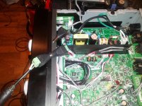
i have an update.
Using a flying connection and a Dell 12V DC refurbished power supply the noise floor looks indeed flatter.
So there must be some issues with the internal power supply that i do not know.
I am seriously thinking about placing a dc socket on the rear of the unit.
I will post the result.
As i said before i notice that the solution of an external ps is quite common for this kind of unit.
It simplify also the unit itself.
Next part will be experimenting with different 12VDC solutions.
Thanks a lot to all for the very kind and valuable advice.
Kind regards, gino
Attachments
Last edited:
Using an external power supply makes some things easier for the engineer designing the product, including meeting noise and interference specifications.Hi !
As i said before i notice that the solution of an external ps is quite common for this kind of unit.
Most customers (myself included) don't like external power supplies, though. Particularly in portable equipment - now you have to carry around two little boxes, instead of one. The external power supply tends to cover up additional AC outlets when plugged in. And the thin wire to supply the power is usually rather fragile, so there's a much higher chance of damaging an external power supply.
-Gnobuddy
Using an external power supply makes some things easier for the engineer designing the product, including meeting noise and interference specifications
Hi ! thanks a lot indeed for the kind reply.
I have the strong feeling that it is not a problem of radiated noise because at first i tried to move the signal cables running close to the smps (that anyway look shielded) with no effect on the noise.
Then i even disconnect them from the pcb. The spikes were always there. So they were not the cables acting as antennas.
So now my guess is that is low noise coming directly out from the smps
An expert with a scope would be able to spot it quite easily.
So at least i have found an issue.
The noise floor now is quite impressive (with mic gain to zero and open input). Increasing the mic gain increases the noise.
Most customers (myself included) don't like external power supplies, though. Particularly in portable equipment - now you have to carry around two little boxes, instead of one. The external power supply tends to cover up additional AC outlets when plugged in.
And the thin wire to supply the power is usually rather fragile, so there's a much higher chance of damaging an external power supply.
-Gnobuddy
You are very right and actually i would like to find a very silent smps to replace the stock one.
I just need a 12VDC single out, a very common voltage. For the Ampere i guess 2A should be more than enough.
The Dell i am using is a 3A unit refurbished. Quite old but looks like a brick
I will look at Mouser catalog where there are usually also the units datasheets. At least for the best quality brands.
I can always keep the two options placing a dc socket in parallel to the power supply output.
I am quite satisfied because i read about the quality of the AD and DAC converters on board.
Yes i am almost happy
Please if you have any advice for a really nice smps i am all ears.
I am afraid a linear one will not fit in the tight space.
Another crazy idea is to place inside only a very good regulation stage and using an external mains voltage transformer.
Thanks a lot again for the kind support and the very valuable advice.
Kind regards, gino
Last edited:
I think your ARTA software should be able to measure the noise from the power supply. Put a small capacitor (say 1 uF, film cap) in series, so that DC voltage from the power supply is blocked by the capacitor, and only the AC (noise) gets through.An expert with a scope would be able to spot it quite easily.
This is normal and expected, and there is something to be learned from this observation.The noise floor now is quite impressive (with mic gain to zero and open input). Increasing the mic gain increases the noise.
The smallest audio signal is at the (mic) inputs. Because the signal is very small, this is the place where it is hardest to get a really good signal to noise ratio. The electronics has to have really low noise to keep it well below the really small audio signal.
That means the input stage is always the noisiest stage in a well-designed preamp. That in turn, means that the total noise from any properly designed audio amplifier (including your TEAC interface) will be dominated by the noise from the input stage (mic input stage).
With mic gain at zero, you are measuring only the noise from the later stages of the preamp. This looks impressively low, but it's not going to be the major source of noise. It does not really reflect the performance of the unit, since you cannot actually use this device with the mic gains turned down to zero!
When (if) you actually use this circuit to record audio, the electronic internal noise will be dominated by the mic input stage. That is the electronic signal-to-noise ratio that actually matters.
I keep using the word "electronic", because even the mic input isn't the biggest source of noise in the recording. There is almost always a much bigger source of noise: the acoustic noise in the room or environment where you are making the recording.
When you connect a microphone to the input and make a recording of the "silence" in the room, it's amazing how much acoustic noise you will typically find. For example, you may hear the refrigerator humming in the kitchen, two or three rooms away. And the cooling fan inside the PC connected to the TEAC interface. And the room air-conditioning or heating. And your neighbour's cats saying "miaow!"
My experience is that with home recordings, this acoustic background noise is always much, much, worse than the electronic noise from any microphone preamp, even a cheap one. Because of this, I hardly care what the advertised signal to noise ratio of my mic inputs is. It really doesn't matter, because the electronic noise will be inaudible, buried in the background acoustic noise around the microphone.
Honestly, I don't think I'm the right person to give you that advice - because I get all my SMPS from the local thrift-stores, and I usually pay only about $2 for each one!Please if you have any advice for a really nice smps i am all ears.
The fact is, these days our electronics is usually not the limiting factor in the quality of our music. So I simply don't care about advertised things like 24-bit A/D converters and 192 kHz clock rates and -115 dB signal-to-noise ratios. As far as my ears can tell, none of it matters at all!
(And it's not that I have bad ears, it's just that a lot of people hear things that aren't actually there, or simply believe "more is better" when it comes to paper specifications.)
-Gnobuddy
- Status
- This old topic is closed. If you want to reopen this topic, contact a moderator using the "Report Post" button.
- Home
- Amplifiers
- Power Supplies
- SMPS _ shielding options.