@ padamiecki:
the file is write protected, the ops contain doubles -that stop tran from working, V(out) is not placed where one would expect and the dimensioning is not well -check the currents with .tran simu)
thank you for the remarks, please write explanations at pm to not rubbish the thread (not simexpert ;-)) or send asc file to the thread
I wasn't sure where to put this question on the site, but since it could be used as an output stage I thought Amplifiers and Solid State would suit it.
Has anyone used, or looked at a Darlington as a main part of a CFP output stage? So that would be three transistors; one cascading into the other and a CFP wrapped around it?
I am a very big fan of CFPs in general and have used them in high power regulators. They seem to lighten up the clumsiness of big power transistors and the local feedback really appeals to me.
The two applications I would be looking at are as plain output sections in either and amplifier or a voltage regulator - though probably the regulator first. Though I know that Douglas Self abhors packaged Darlingtons (and I do take his point) but there is a huge temptation to use one of those high current packages where you have a Darlington with two power devices in the same box (preferably not TO-3). Does anyone have any idea what might be a suitable choice?
Many thanks, Christian
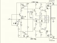
Yes, Linsley-Hood designed power amplifiers in the 70's that used a power darlington pair MJ2501 and MJ3001 in combination with BC447 and BC448 the latter in common emitter mode driving the darlingtons whose emitter connections were to the supply voltage and earth (or negative rail).
A constant current load and common emitter amplifer was the main voltage stage and due to the former there was no need for a voltage multiplier to set the output stage current - a resistor was good enough for the job.
In 1980 he published a design he thought an improvement over these where the darlington pairs were replaced by the classic Hitachi MOSFET's.
Hood also used darlingtons for regulated power supplies.
You should be able to find plastic encapsulated darlingtons of suitable rating to replace the metal can MJ types which are pretty rare and costly.
Hi Guys
It is not unusual to have very wide and flat frequency response for open-loop output stages, or even for simple complete amplifiers. The extended open-loop response for the output stage would suggest that it can be enclosed in a feedback loop with little problem... that is where the fun begins.
Elvee's experiment is well done.
Three-device compounds for output stages have been explored since the earliest days of solid-state. Blomley had a good discussion of them, as did Walker and Linsley-Hood. Back then, they had to caclulate things the hard way and even do measurements to gain the insights we garner in a few minutes with spice.
As is well understood, integrated Darlingtons have been and always will be a performance reducer only good at meeting an economic goal.
Have fun
Hi Guys
It is not unusual to have very wide and flat frequency response for open-loop output stages, or even for simple complete amplifiers. The extended open-loop response for the output stage would suggest that it can be enclosed in a feedback loop with little problem... that is where the fun begins.
Elvee's experiment is well done.
Three-device compounds for output stages have been explored since the earliest days of solid-state. Blomley had a good discussion of them, as did Walker and Linsley-Hood. Back then, they had to caclulate things the hard way and even do measurements to gain the insights we garner in a few minutes with spice.
As is well understood, integrated Darlingtons have been and always will be a performance reducer only good at meeting an economic goal.
Have fun
Having two forward biased emitter junctions within one structure is like having the cook put his head into the oven. That is not to say the problem cannot be addressed by using a different output stage configuration.
That was Linsley-Hoods approach in 1975 having looked at structures such as the Quad 303 and Locanthi T-circuit triples among others. His article "Amplifier Technology" in the June issue of ETI for that year refers.
Hood's article shows transfer characteristics of various output stage forms - not one of these showed better linearity than his design.
If the output stage transfer characteristic has identical slopes on opposite axis and the congruence at the crossover point is very close there should be less crossover distortion to start with and if the basic linearity is maintained up to "several hundred KHz" this has to be a plus in consideration of NFB and stability margins.
It would be interesting to see a SPICE comparison of this with a Locanthi triple if anyone has the inclination and time.
Hi,
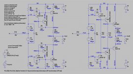
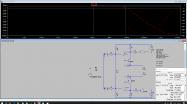
attached my sims of CFP-Triple versus Locanthi-Triple.
Bias points simmed so that the idle currents are similar.
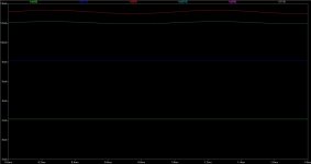
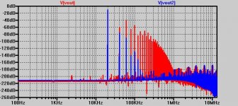
Both show nearly the same amplitude response, bandwidth and peaking wo. the compensation caps as welll as the peak-less response with the caps installed.
No clear advantage for any of which in this regard.
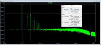
THD-values of both circuits are of similar mean value but the CFP-Triple showing more higher order harmonics, especially at higher signal voltages and currents.
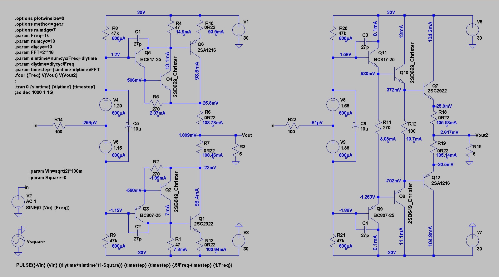
In Pic1 one can see that the bias voltages for the CFP-Triple are lower (by roughly 1xVbe per half) and of nearly equal value, while with the T-circuit they differ considerably.
Looking at the idle currents the CFP though differs more between its lower and upper half.
Very obvious with the second transistor pairs Q2/Q4 versus Q8/Q10, where they nearly differ by a factor of 2.
The currents of the T-circuit´s halfs are very similar.
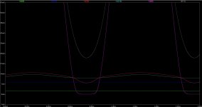
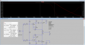
The following three curves show the transistor currents of the upper half transistors [rem. I(R18)=Ie(Q7)] when fed from a 1kHz rectangle of +-141.4mV +-1.414V and +-14.14V.
At 141.4mV (pic2) the currents of the two first transistor pairs are nearly constant.
Still though on can see that the ´excursions´ of the T-circuit are slightly lower.
The curves of the output transistors Q6 and Q7 are beyond the scale here, idling at ~95mA and 105mA.
At 1.414V (pic3, larger scale) the larger current swings of the two first transistor pairs of the CFP becomes obvious.
While the curvature of Q10 is still of a sinusodial shape Q4 shows a drop in the region where the output transistor Q6 runs into cutoff.
rem: Q6 is already working under cutoff conditions due to its lower idle current than Q10.
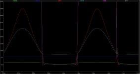
At 14.14V (pic4) not only the the output transistors Q10 and Q7 cut off, but also the second stage transistor Q4 of the CFP.
In that region its current curvature is close to a unsteadyness, a step.
Even the input transistor Q5 shows a beginning drop in that region.
The T-circuits first and second stage remain biased and the curvature still look sinusodial.
Also the output transistor Q10 of the CFP transits into cutoff and out of cutoff sharply, while Q7 of the T-circuit shuts down and opens up much softer.
No wonder that the CFP´s THD diagram shows alot more higher harmonics.
Even though the THD mean value of both circuits don´t differ much, the lesser higher harmonic part and the more ´friendly´ appearing current curves clearly speak in pro for the T-triple.
The CFP requires less biasing voltage and is probabely a bit easier to bias and to stabilize thermally, and it allows for slightly higher clipping voltages.
But from this simulation the T-circuit looks preferrable to me.
jauu
Calvin
attached my sims of CFP-Triple versus Locanthi-Triple.
Bias points simmed so that the idle currents are similar.
Both show nearly the same amplitude response, bandwidth and peaking wo. the compensation caps as welll as the peak-less response with the caps installed.
No clear advantage for any of which in this regard.
THD-values of both circuits are of similar mean value but the CFP-Triple showing more higher order harmonics, especially at higher signal voltages and currents.
In Pic1 one can see that the bias voltages for the CFP-Triple are lower (by roughly 1xVbe per half) and of nearly equal value, while with the T-circuit they differ considerably.
Looking at the idle currents the CFP though differs more between its lower and upper half.
Very obvious with the second transistor pairs Q2/Q4 versus Q8/Q10, where they nearly differ by a factor of 2.
The currents of the T-circuit´s halfs are very similar.
The following three curves show the transistor currents of the upper half transistors [rem. I(R18)=Ie(Q7)] when fed from a 1kHz rectangle of +-141.4mV +-1.414V and +-14.14V.
At 141.4mV (pic2) the currents of the two first transistor pairs are nearly constant.
Still though on can see that the ´excursions´ of the T-circuit are slightly lower.
The curves of the output transistors Q6 and Q7 are beyond the scale here, idling at ~95mA and 105mA.
At 1.414V (pic3, larger scale) the larger current swings of the two first transistor pairs of the CFP becomes obvious.
While the curvature of Q10 is still of a sinusodial shape Q4 shows a drop in the region where the output transistor Q6 runs into cutoff.
rem: Q6 is already working under cutoff conditions due to its lower idle current than Q10.
At 14.14V (pic4) not only the the output transistors Q10 and Q7 cut off, but also the second stage transistor Q4 of the CFP.
In that region its current curvature is close to a unsteadyness, a step.
Even the input transistor Q5 shows a beginning drop in that region.
The T-circuits first and second stage remain biased and the curvature still look sinusodial.
Also the output transistor Q10 of the CFP transits into cutoff and out of cutoff sharply, while Q7 of the T-circuit shuts down and opens up much softer.
No wonder that the CFP´s THD diagram shows alot more higher harmonics.
Even though the THD mean value of both circuits don´t differ much, the lesser higher harmonic part and the more ´friendly´ appearing current curves clearly speak in pro for the T-triple.
The CFP requires less biasing voltage and is probabely a bit easier to bias and to stabilize thermally, and it allows for slightly higher clipping voltages.
But from this simulation the T-circuit looks preferrable to me.
jauu
Calvin
Attachments
Last edited:
Calvin, could you possibly upload the asc for that, along with the models you have used for the hitachi and Sanken parts.
A few things. We seem to have lost the initial advantage of the circuit as done by Elvee, which was that we didn't have the peaking and, with the Darlington-in CFP seemed to have lost at least one pole, which would give it a huge advantage when it comes to inserting feedback.
Obviously part of that is the components chosen and probably some examination of the models would show that up, but there must also be a mechanism that allowed such a smooth roll off with this circuit in the first cases, when it wasn't showing in the others. My guess is that the capacitances of one of the pairs somehow melded into one. Though we should put in nice fast components, it does seem a bit silly to then have to go and compensate for them. That peak requires an inductive element to be there at all and, though the capacitances will show up as inductive impedances, I'm just wondering where it comes from.
It might be that the behaviour we are seeing are component values being used. Q6 cutting off being highlighted. The Iq through R4 looks very much like the Vbe drop across Q6. 0.7V/47R = 14.89mA. I assume that's not going to change except as the Vbe widens, though other things might be jostling. So it does look to me as though it just isn't going to provide enough base current.
I wonder if something similar had been going on in the sandwiched CFP as we inadvertently set up current sources.
Hi,
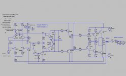
here http://www.diyaudio.com/forums/atta...und-pair-cfp-triple-vers-locanthi-t-schem.jpg
allowed one small mistake. Output stages always operate from a VAS - signal source with high output impedance, at least several tens of kilo Ohm. For a correct simulation it is necessary to remove the resistors R8, R9 and R20, R21 47 kilo Ohm (enough voitage generators V4, V5 and V8, V9), and in the settings of the signal source V2, the output resistance is set equal to 100 kilo Ohm.
i am missing the then famous Quad triple compound
I had a look at those too. Here is are various takes on the theme.
Attachments
The peaking has come down here. It's very dependent on quiescent which I have kept around 100mA, but which changes with the components.
Newer transistors seem to sometimes work and sometimes not, so mje243/253 make it worse but that could have been an oversight somewhere. I would like to try some Zetex pre drivers. Most important in bringing it down was reducing the R4 and R1 to 10R. That might get a bit hot. Ideally I'd like to get the emitter resistors down too. Once there's something acceptable here then I'm going to try the sandwiched CFP.
Edit. I think these are all using Cordell models.
Attachments
Comparing the standard EF and Sziklai when the output voltage is approximately 400 mV showed the advantage of the first of them at 32...40 dB on the linearity.
With increasing output voltage the advantage of the usual follower remains, but not that big.
With increasing output voltage the advantage of the usual follower remains, but not that big.
Attachments
I had a look at those too. Here is are various takes on the theme.
Unfortunately or fortunately, but these circuitry was very advanced at the time when there were no complementary pairs of high current output transistors. Now we are provided with them and no longer need in this schematic.
Comparing the standard EF and Sziklai when the output voltage is approximately 400 mV showed the advantage of the first of them at 32...40 dB on the linearity.
With increasing output voltage the advantage of the usual follower remains, but not that big.
I just don't follow you at all on this. The distortion is going to be so dependent on quiescent current that you can't just pick a circuit out of the air and say that's how it performs. As for standard EF versus Sziklai, the argument has always been marginal and there are things that can be done to speed up switch off. I certainly don't remember Douglas Self dismissing the CFP out of hand.
Anyway, the point here is to get something that is nicely behaved in the rolloff (which I have managed to get back to with a few changes to that circuit posted above - which I will get to posting with a comparison) and see if it can be better in terms of stability. Initially I wanted to look at the sandwiched CFP until this one showed such promise and thought that might show a more stable output impedance under load and on each half. So this is not just about distortion.
attached my sims of CFP-Triple versus Locanthi-Triple.
Bias points simmed so that the idle currents are similar...
Hi Calvin
Looks like the idle currents of the pre-drivers are not very similar - ~2 mA compared to ~ 8 mA?
Best wishes
David
Hi,
attached my sims of CFP-Triple versus Locanthi-Triple.
Bias points simmed so that the idle currents are similar.
Both show nearly the same amplitude response, bandwidth and peaking wo. the compensation caps as welll as the peak-less response with the caps installed.
No clear advantage for any of which in this regard.
THD-values of both circuits are of similar mean value but the CFP-Triple showing more higher order harmonics, especially at higher signal voltages and currents.
In Pic1 one can see that the bias voltages for the CFP-Triple are lower (by roughly 1xVbe per half) and of nearly equal value, while with the T-circuit they differ considerably.
Looking at the idle currents the CFP though differs more between its lower and upper half.
Very obvious with the second transistor pairs Q2/Q4 versus Q8/Q10, where they nearly differ by a factor of 2.
The currents of the T-circuit´s halfs are very similar.
The following three curves show the transistor currents of the upper half transistors [rem. I(R18)=Ie(Q7)] when fed from a 1kHz rectangle of +-141.4mV +-1.414V and +-14.14V.
At 141.4mV (pic2) the currents of the two first transistor pairs are nearly constant.
Still though on can see that the ´excursions´ of the T-circuit are slightly lower.
The curves of the output transistors Q6 and Q7 are beyond the scale here, idling at ~95mA and 105mA.
At 1.414V (pic3, larger scale) the larger current swings of the two first transistor pairs of the CFP becomes obvious.
While the curvature of Q10 is still of a sinusodial shape Q4 shows a drop in the region where the output transistor Q6 runs into cutoff.
rem: Q6 is already working under cutoff conditions due to its lower idle current than Q10.
At 14.14V (pic4) not only the the output transistors Q10 and Q7 cut off, but also the second stage transistor Q4 of the CFP.
In that region its current curvature is close to a unsteadyness, a step.
Even the input transistor Q5 shows a beginning drop in that region.
The T-circuits first and second stage remain biased and the curvature still look sinusodial.
Also the output transistor Q10 of the CFP transits into cutoff and out of cutoff sharply, while Q7 of the T-circuit shuts down and opens up much softer.
No wonder that the CFP´s THD diagram shows alot more higher harmonics.
Even though the THD mean value of both circuits don´t differ much, the lesser higher harmonic part and the more ´friendly´ appearing current curves clearly speak in pro for the T-triple.
The CFP requires less biasing voltage and is probabely a bit easier to bias and to stabilize thermally, and it allows for slightly higher clipping voltages.
But from this simulation the T-circuit looks preferrable to me.
jauu
Calvin
In your CFP model Q4 passes roughly double the current of Q2. These currents should be in balance. If you revise this I would appreciate seeing an amended version as well - this as per the CFP output in the first image in post 50.
... that is nicely behaved in the rolloff ... and see if it can be better in terms of stability...more stable output impedance under load and on each half. So this is not just about distortion.
There are some complexities here.
Simple feedback theory is applicable if there is one point that can cut all the feedback - and that doesn't apply here, there is internal feedback around the various CFP loops and an EF is essentially 100% local NFB.
So the correlation between frequency peaks and stability is not certain, which is a bit of a worry.
I suspect this explains many problems that people have had with CFP stability.
Similarly the distortion and output impedance usually track, there's a nice article by Dr Cherry on this that compares EF with CE outputs, but I am not sure how it works here.
Best wishes
David
Last edited:
These are the distortion components I'm getting from a circuit only slightly modified from the one I posted earlier. It's not balanced to perfection but is within a few mA. The worst component is ~94dB down. I haven't looked at output stages this closely before but I would have thought that it was pretty good for something without a feedback loop.
I was going to post a comparison but I'll post this circuit and asc as an interim.
PS This is about 400mV of output.
I was going to post a comparison but I'll post this circuit and asc as an interim.
PS This is about 400mV of output.
Attachments
There are some complexities here.
Simple feedback theory is applicable if there is one point that can cut all the feedback - and that doesn't apply here, there is internal feedback around the various CFP loops and an EF is essentially 100% local NFB.
So the correlation between frequency peaks and stability is not certain, which is a bit of a worry.
I suspect this explains many problems that people have had with CFP stability.
Similarly the distortion and output impedance usually track, there's a nice article by Dr Cherry on this that compares EF with CE outputs, but I am not sure how it works here.
It took me a moment to catch your meaning here. it doesn't help that I keep forgetting that an EF has local feedback (I need a loop to remind me
") ). Doesn't cutting it between the emitter resistor and the main driver - or putting a resistor in there - do it? But I'm in no doubt that it's going to be complex!
). Doesn't cutting it between the emitter resistor and the main driver - or putting a resistor in there - do it? But I'm in no doubt that it's going to be complex! That article sounds like just the sort of thing I'd want to look at. I'm sure it would be quite closely related to this. The slightly simplistic way I'm envisaging this working is that you are still getting the product of the hfes but on top of that a geometric mean for the transition frequency. I see that as hopefully the chief advantage here, but I'm sure there's more to it than that because I have seen some kinks around the knee of the rolloff during simulation, so the capacitances aren't interacting that straightforwardly. Then I imagine the darlington-in is just giving us a high beta driver.
The proportion of imagination to understanding here might be a bit high.
Christian
- Status
- This old topic is closed. If you want to reopen this topic, contact a moderator using the "Report Post" button.
- Home
- Amplifiers
- Solid State
- A three transistor compound pair?