Because, when the shouting has died down, and everyone has gone home -- if the sound is just not right then you'll still be aware of such. So then you need to find other culprits -- formats aren't good enough, recordings weren't done 'properly', etc, etc ... whatever's needed to keep the hounds at bay ...Why do you keep dismissing the importance of Faery Dust?
")
I like to get the best out of a TV picture, and sharpness can be a tricky one to optimise. Exploring a couple of days ago, people were discussing what the setting should be - and mention was made that 'experts' had stated that Sharpness should be 0 - anything else was artificially enhancing the picture, 'fake' detail was being added. And so some people dutifully did exactly that - but the picture didn't look as good. They were told, "Get over it!, the picture is now optimum, that's as good as digital TV gets ...".
Trouble is, the manufacturers play games - the 'Off' position can be anywhere in the scale - zero could be quite a large 'negative' sharpness, the picture is processed to add blurring.
But, some people dutifully put up with an inferior picture, bcause the authority figures had told them 'how it was' ...
Bad experts, then. Those I learned from said that sharpness is usually turned up too high, so here are some test patterns to set it correctly. Some signals need a little high frequency boost, VHS for example. Things are different in the digital age, but you should still test, not just go by what you've been told.
If skin effect can provide a useful dampening effect at RF to absorb RFI, then it's possible it can make a difference, especially if the amp is unstable. Just sayin. Dynamic oscillation in amps can make audible differences between components that shouldn't make any difference.
Of course this suggests skin effect is a GOOD thing, not a bad thing.
Has anyone ever tried 300R or 450R ribbon cable for speaker wires?
Of course this suggests skin effect is a GOOD thing, not a bad thing.
Has anyone ever tried 300R or 450R ribbon cable for speaker wires?
In LTspice, use a vcvs (voltage controlled voltage source). I believe its model is called E.
~Tom
Thanks, Tom. That is actually what I have been doing.
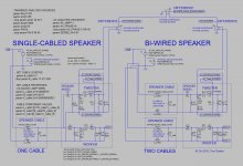
Attached is a cleaned-up version of the schematic and its corresponding LT-Spice .asc file.
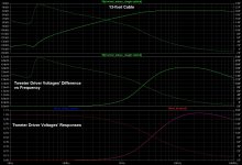
Plots of differences between tweeter driver voltages for bi-wired and single-cabled are also attached.
I will let someone who knows more about this stuff, like bolserst, show plots of things like on-axis response differences, if desired.
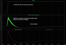
Edit: I also temporarily used a time-domain pulse source for each speaker (with all other sources disconnected) and applied a 6-Volt step with a 10 µs rise-time, and plotted the difference of the two tweeter driver input voltages.
Cheers,
Tom
Attachments
Last edited:
Is this why RF inductors are often wound with Litz?
I thought that was only 'audiophile' classD output inductors being wound with speaker wire, and a mistake
I disconnected all of the voltage sources shown in the schematic and added two identical ones (one for each speaker) that use a WAV file for input, with a WAV file containing the intro to Highway to Hell, by AC-DC.
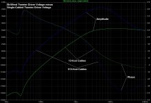
Using 13-foot cables, there is a difference between the bi-wired and single-cabled tweeter output voltages. Plots are attached.
Cheers,
Tom
Using 13-foot cables, there is a difference between the bi-wired and single-cabled tweeter output voltages. Plots are attached.
Cheers,
Tom
Attachments
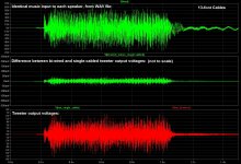
A difference of less than 0,01 dBUsing 13-foot cables, there is a difference between the bi-wired and single-cabled tweeter output voltages.
A difference of less than 0,01 dB
that is just the indication that something else is going on
A difference of less than 0,01 dB
More like 0.06 dB.
How did you get 0.01 dB?
I used 20 log ( 7.05 / 7.00 ) = 0.062 dB.
in my poor english, are you saying the tweeter is missing the other drivers to draw the power ?
I was only comparing the tweeter responses, for bi-wired and single-cabled speakers.
Oops.I see ~50mVpk of difference in a signal of ~5Vpp.
The difference is ~20dB below the tweeter signal.
1/100th is -40dB
I note .0017 ohms per foot, #12awg.I was only comparing the tweeter responses, for bi-wired and single-cabled speakers.
Try 16 guage.
Also, can you open the timebase to discern if it's amplitude or phase, or both that is showing the difference.
jn
Plots of differences between tweeter driver voltages for bi-wired and single-cabled are also attached.
Edit: I also temporarily used a time-domain pulse source for each speaker (with all other sources disconnected) and applied a 6-Volt step with a 10 µs rise-time, and plotted the difference of the two tweeter driver input voltages.
Cheers,
Tom
I believe if you zoom in to the fuzzy difference area, you will find that it is sawtooth in nature, with the same slope as the 10 usec step.
If you halve the tweeter impedance or double the cable impedance, that fuzzy will double in amplitude.
jn
still have the question
While I believe three separate boards are better, than cramming all the components on one board, I still don't understand how bi-wiring would make a difference since the same signal is going to all three boards. Could it be that biwiring eliminates emf from the MF board going through the LF board and then back to the amp?
Would using different awg wires, to the LF and MF/HF, with different capacitance and impedance characteristics, make an improvement in coping with EMF back to the amp? In summary, can selecting optimal wire characteristics for the LF and for the MF&HF be of benefit?
If I got an answer I didn't understand it. Since then I've studied the N803 schematic and understand that each enclosure has three separate crossover boards. The lower binding posts go directly to the LF board and that board's outputs only go to the two woofers. The upper binding posts go to the MF board which is connected to the HF board. Hence the need for jumpers when a single pair of wires, to the amp, are used.Hi Cal,
My B&W N803s each have 4 binding posts, which lead me to believe each speaker has an LF filter for the woofers and a HF xover, for the mid range to tweeter. If, in fact, the LF filter and HF xover are connected to each other why are jumpers needed? Conversely, if they are not connected to each other, why wouldn't bi-wiring be of some benefit? What am I not understanding?
Thanks,
henrylrjr
While I believe three separate boards are better, than cramming all the components on one board, I still don't understand how bi-wiring would make a difference since the same signal is going to all three boards. Could it be that biwiring eliminates emf from the MF board going through the LF board and then back to the amp?
Would using different awg wires, to the LF and MF/HF, with different capacitance and impedance characteristics, make an improvement in coping with EMF back to the amp? In summary, can selecting optimal wire characteristics for the LF and for the MF&HF be of benefit?
Way back in post 9 somebody said this:
Smart guy.
Theoretically it is difficult to make an argument for bi-wiring but if you notice a difference and you appreciate the difference, who is to argue?
Audio subjectivity goes much further than bi-wiring. Keep yourself happy, it's all that matters.
Smart guy.
- Status
- This old topic is closed. If you want to reopen this topic, contact a moderator using the "Report Post" button.
- Home
- Loudspeakers
- Multi-Way
- What does the crossover do differently when you bi-wire?