
New parts arrived. All done.
Good Job!
")
And perfectly clean boards, nice
Let us know how it sound
With PTF56 in R101, R201 it's possibile that it will sound a bit 'bold', the last BOM specify RN55 for those positions.
Good Job!
And perfectly clean boards, nice
Let us know how it sound
With PTF56 in R101, R201 it's possibile that it will sound a bit 'bold', the last BOM specify RN55 for those positions.
Will be 1-2wks before any listening tests, but I'll report my findings here.
Yeah, I have a box of parts from keeping up with the recent changes and I couldn't bring myself to desolder R101,R102. Soldered them in literally hours before the last BOM was released. Sometimes discretion really is the better part of valor when it comes to PCBs. That'll be the first place I look if it sounds too bold, but actually I kinda like that description!
BK
thanks for the explanation dario, all clear now and yes i do have the amtrans.
this is my first time trying to calculate heatsink size.
For heatsink calculation i used the formula supplied in lm3886 spec sheet. The P DMAX is from fig. 36 for 8Ohm load.
θ SA = [(T Jmax − T Amb ) − P DMAX (θ JC + θ CS )]/P DMAX
θ SA = [(150 − 30 ) − 23 (1 + 0,2)]/23 --> 4 °C/W
Is this calculation right?
and yes i do have the amtrans.this is my first time trying to calculate heatsink size.
For heatsink calculation i used the formula supplied in lm3886 spec sheet. The P DMAX is from fig. 36 for 8Ohm load.
θ SA = [(T Jmax − T Amb ) − P DMAX (θ JC + θ CS )]/P DMAX
θ SA = [(150 − 30 ) − 23 (1 + 0,2)]/23 --> 4 °C/W
Is this calculation right?
Last edited:
Yes but that applies to driving a full level sinewave continuously and just keeping Tj at ~150°C.
Are you reading 23W for the ±25Vdc @ 30W of output power?
With music there is much less dissipation and that results in lower Tc.
I use the graph (Figure 34.) in the 3886 datasheet and then double the recommended heatsink to keep temperatures low and thus have fewer triggers where "Spike" limits current output.
Last edited:
thanks for the explanation dario, all clear now
(...)
Is this calculation right?
You're welcome.
For the calculation I think Andrew already answered extensively.
The My_Ref doesn't genereate a lot of heat, dissipating sides of HiFi2000 Slimline cases are enough for it.
This one will be perfect:
Slim Line 02/350 2U 10mm ARGENTO
andrew: thanks again for clarifying.
so i tried calculating myself
dario: yeah i was thinking about that case but since I blew my budget I was thinking i might use the case of an old amp until i have saved some more money *g*
P.S. your price for smd soldering is really cheap. Did it myself today and it was a real pain *g* Was my first time doing smd, hopefully i didn't f*** something up
yes. Looking again i realized i looked at the wrong curve (Vs=30). It should be more like 15 I guess. I was confused by fig. 34Are you reading 23W for the ±25Vdc @ 30W of output power?
so i tried calculating myself dario: yeah i was thinking about that case but since I blew my budget I was thinking i might use the case of an old amp until i have saved some more money *g*
P.S. your price for smd soldering is really cheap. Did it myself today and it was a real pain *g* Was my first time doing smd, hopefully i didn't f*** something up
Current Amp
Hello,
I am in the proces of building 2 stereo my_ref_fremen editions for my 4-way DSP controlled active speakers. After reading an interresting artikel of Esa Merilainen about the advantages of a current drive amplifier ( Current-Drive - The Natural Way of Loudspeaker Operation ) I am playing with the idea to convert one of the amplifiers for the mid-range section to current drive.
Has anyone an idea how i can do this the easy way?
I use fig34 as I find that both quick and easy.................... I was confused by fig. 34
Go to the right hand end and select your PSU voltage. Go up till you intersect your speaker impedance. Go left until you reach your heatsink's Ta and read off the NS recommended heatsink Rths s-a. Interploate if you are between values.
But, that NS recommendation is for highest dissipation from the chip (about 2/3rds maximum output sinewave power) while the chip temperature is at 150°C. i.e it won't be damaged. The chip is bolted direct to the heatsink (Rth c-s=0.2C/W)
It will not reproduce any signal if the over-temperature detector kicks in, or the "Spike" current limiter kicks in.
You NEED to run the chip MUCH cooler if you don't want "Spike" to current limit on transients when other large but acceptable signals have warmed up the chip. I arived at a compromise that keeps the chip cool and allows the chip to reproduce loud music. I double the size of the heatsink.
ex.
PSU ±30Vdc when loaded
Speaker 8ohms
Heatsink Ta=25°C
go along to 60Vdc and upto 8ohms. You find the intersection at two and a half squares up. Now go all the way left to Ta=25°C. you are between 5.1C/W and 3.8C/W The interpolated value is ~4.4C/W.
Now double the heatsink size to arrive at 2.2C/W per channel.
Two channels of 8ohms on 60Vdc (loaded) ~±34Vdc (quiescent) requires a 1.1C/W and gives an allowance for warm summer temperatures upto 30°C when the heatsink is mounted external to the enclosure.
If you don't accept my doubling of heatsink size, then use 4.4C/W for each channel.
Last edited:
wow andrew, thanks a lot for that detailed explanation. It helped a lot. I was just thrown off by the table because ambient temps go up to 110 °C. I assumed there would be no sense in have calculations for temperatures that high Well, now i know better.
Thanks also for explaining why to double heatsink size. So if I use a ±24V transformer that would give me roughly ±34 V --> 68 Vcc after rectification so my 3.2 °C/W heatsink would be good for testing but not suitable for long term use.
Well, now i know better. Thanks also for explaining why to double heatsink size. So if I use a ±24V transformer that would give me roughly ±34 V --> 68 Vcc after rectification so my 3.2 °C/W heatsink would be good for testing but not suitable for long term use.
Would someone be so kind to have a quick look at the attached pictures? I am afraid i messed the position of R10 up. I thought i did it the same way as bk856. But it seems that then the connection is broken... I should have checked before soldering. Could I try to simply make a solder bridge to the pin on the left? I really would like to avoid unsoldering the resistor.
Attachments


Last edited:
Would someone be so kind to have a quick look at the attached pictures? I am afraid i messed the position of R10 up. I thought i did it the same way as bk856. But it seems that then the connection is broken... I should have checked before soldering. Could I try to simply make a solder bridge to the pin on the left? I really would like to avoid unsoldering the resistor.
I'm sorry but you have to desolder it...:
As is now, in practice, it is shorted.
You must use the pads into the box.
Attachments

*lol* should have realized that myself. Damnit. Anyway, thanks for the reply.
You're welcome
Clemens... did you see this post?
Your R11 is reversed, it should by this way (orientation):
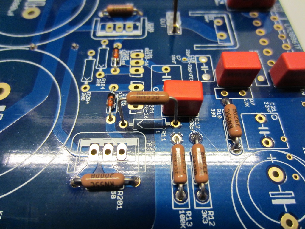
You should desolder and reverse it.
Can you post a pic from a side?
I fear that the Amtrans are also reversed...they should be this way:

Your R11 is reversed, it should by this way (orientation):
You should desolder and reverse it.
Can you post a pic from a side?
I fear that the Amtrans are also reversed...they should be this way:
Attachments

Last edited:
Hey Dario,
thanks for letting me know about R11. Must have overlooked the post. Damnit, i hate desoldering. R10 is now crooked but fixed ;-)
The Amtrans should be the right way. The writing faces the circle just like in your picture. Somehow you can't really see the writing in my pics. Will fix R11 and post pictures afterward. Hope my soldering quality isn't too bad. had quite some trouble figuring out the right temp. I needed almost 330°C and was too hesitant in turning up the temp *g* Might be that the temp display is wrong, its a pretty cheap one ;-)
About soldering the lm3886s ... is it curcial to fix it on the heatsink before soldering? Since i wanted to test the amp before ordering the final housing i would use another heatsink...
Last edited:
hi again, i tried now for almost 1,5 hours to desolder r11 ... got 1 leg free but the one on the ground plane is impossible to get out ... even tried it with chipquick. problem seems that the lead has flown to the "top" side of the board and i cant suck it out... solder braid doesn't seem to suck it out as well ... is it really that crucial?...
... got 1 leg free but the one on the ground plane is impossible to get out ... even tried it with chipquick. problem seems that the lead has flown to the "top" side of the board and i cant suck it out... solder braid doesn't seem to suck it out as well ... is it really that crucial?...
Last edited:
thanks for letting me know about R11.
You're welcome
Hope my soldering quality isn't too bad. had quite some trouble figuring out the right temp. I needed almost 330°C and was too hesitant in turning up the temp *g*
From the pics looks good and clean.
Are you using lead free solder? If so even 340°C could be necessary.
About soldering the lm3886s ... is it curcial to fix it on the heatsink before soldering? Since i wanted to test the amp before ordering the final housing i would use another heatsink...
It would be better but if must solder them now use the same heatsink and fixing hole for soldering both so you have identical position for both boards.
hi again, i tried now for almost 3 hours to desolder r11
Simply pull off gently the resistor while you mantain molten the solder with the iron, try to do it in not too much time to avoid damage on the pad.
From the pics looks good and clean.
good
Are you using lead free solder? If so even 340°C could be necessary.
nope, thats what seems strange to me. using an eutetic Sn/Pb/Ag mix.
It would be better but if must solder them now use the same heatsink and fixing hole for soldering both so you have identical position for both boards.
ok, will try to be patient and wait for the case first *ggg*
Simply pull off gently the resistor while you mantain molten the solder with the iron, try to do it in not too much time to avoid damage on the pad.
tried that already but it seems its not melting on the other side. Didn't dare to apply heat for more than 4-5 seconds at 370° (kinda seems long to me already). Do you think i should try heating longer?
- Home
- Amplifiers
- Chip Amps
- My_Ref Fremen Edition - Build thread and tutorial