Curious to learn specifics of what helped.
- Windowing the far field for HF response to 3-5ms. Minimum frequency as a function of windowing.
- Far field is not that far, 3ft. is usually enough.
- LF measurement in near field, with a large window. Max frequency as a function of effective driver radius.
- How to add the multiple woofers response (no, responses are not identical, the woofer position seriously impacts the LF response) and the port response.
- Splicing/blending the HF and LF response to get the anechoic overall response.
- Minimum phase extraction procedure.
Interesting stuff, I wish I had the time and means to further study. Appears much more complex than audio electronics design, and the results are much more audible, I guess.
Last edited:
Putting it all together
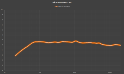
The owner of the B&W 802 Matrix S80 (purchased before I was born) decided to upgrade the crossovers, essentially get rid of the bunch of non polarized electrolytics (drying out) and install polypropylene caps all over (except of a 1000uF isolating the woofers against DC, which he removed completely). I mildly protested, since I thought (not having any experience with speakers design) that missing the electrolytics ESD may significantly alter the frequency response.
After investing a good two tons into caps, and some stunts to make them fit in the tight space under the baffle, he declared himself happy with the results (based on his listening results). I took the opportunity and measured his B&Ws with rebuilt crossovers, and below is the result. After a few false starts, I think I got it pretty good. I have no idea what the frequency response was before the surgery, but it appears to me that the upgrade was pretty successful. In this measurement I've put all the learning above together, including the baffle diffraction simulation.
His other pair of monster Infinity Kappa 100 towers (17" x 58", 150lb. each) measurement was less successful, and I believe the unusual cabinet geometry (they are trapezoidal in a horizontal section, so what would be the baffle edge radius?) and the large number of drivers (2x12" woofers, 1x6.5" mid-woofer, 1x4.5" mid and an about 5cm^2 ribbon tweeter) are making the measurements difficult. I suppose these need a much larger distance to integrate the far field response, which in turn increases the room reflections contributions, plus that the woofers (subwoofers, really) are crossing at less than 200Hz). I will try to get better results when I'll have a chance.
Now I can handle my friends bookshelf speakers measurement with more confidence.
Attachments
Good job waly. Looks like you are well on your way. Did you use the Omni-mic system to generate the trace in your last post? It doesn't look like an Omni-mic trace. I'm more used to one's that look like Sy's in post #6.
For the purpose of learning, I was bringing all the data to Excel. The flow was:
- Measure the far field and near field responses in Omnimic. Export data to frd files.
- Import all near field frd's in Excel and plot them above the minimum frequencies corresponding to the impulse window size. Compare the sum of near field responses with the far field response.
- Import data in the FRD Response Blender Excel spreadsheet.
- Input the cabinet geometry in the FRD Response Blender and simulate the LF diffraction correction.
- Level the LF response and calculate the minum phase response.
- Export the frd and import in an Excel spreadsheet for plotting.
.......
I just got D'Appolito's book, maybe he'll help rain down knowledge and have it stick where others have failed to in this area.
Best,
Erik
If you are referring to D'Appolito's 'Testing Loudspeakers' book, I have that too, but never found it very useful. If's full of very technical explanations and formulas, but what he forgot to include was how to interpret the data. He ended up publishing a couple of supplementary documents that address the book's lack of data interpretation advice. IIRC, they can be downloaded for free if you do the right Googling.
Found these, answering my own question:
http://www.klippel.de/fileadmin/kli...ement_with_Multiple_Drivers_ and_Ports(2).pdf
http://www.klippel.de/fileadmin/kli...39_Merging_Near_and_Farfield_Measurements.pdf
The port response has to be considered as well.
I know now how to add the port response to the overall LF response. However, what if the port is back firing? Are there any specifics to consider compared to a front firing port?
It appears to me there's a conflict here. While we are trying to use the LF near field response to avoid room reflections, the back firing port relies exactly on reflections to add to the overall SPL at the listening position. If I could measure such a speaker in an anechoic room then the back port response contribution to the overall response would be zero, right?
When I measure either front or rear port response, I stick the mic right into the port and get the ultimate NF response measurement.
As far as perhaps phasing issues with front vs rear reflecting issues, those are more design considerations and measurement considerations.
Yes, the port response should be measured in the middle of the port plane and added to the LF response, pondered by the ratio between the port radius and the bass driver piston radius.
My confusion is about the purpose of including a back firing port response to the overall anechoic speaker response (which is what we are doing by splicing the near field LF response to the gated far field HF response). I an anechoic room, isn't the back firing port response moot, since there are no reflections, so no contribution to the overall speaker response? For a front firing port, no question it should be considered.
Frequencies that low are omnidirectional in a typical speaker (i.e not infinite baffle).
Are you saying that in an ideal anechoic room, a port will have the same contribution to the low frequency response in any point of the room, and for any relative position of the port to the listener? What about the phase delta between the wave fronts (from the front radiator and the back port)?
Are you saying that in an ideal anechoic room, a port will have the same contribution to the low frequency response in any point of the room, and for any relative position of the port to the listener? What about the phase delta between the wave fronts (from the front radiator and the back port)?
Yes, the relative LF contribution from the port will be the same as from the driver, however the absolute energy will not be the same at every point in the room since SPL falls by the inverse square of the distance from the source. This assumes an anechoic 4-pi environment and disregards any interference between port and driver (which is a different issue but shouldn't be a big problem as long as they are within 1/3rd of a wavelength of the relevant LF of each other).
Ok, so here's my friends speakers (project codename "Cheapo") saga. The speakers he built are small closed box cabinets (about 8 liter), pre-built. Drivers are a Dayton woofer DC130AS-8 and an Airborne UR74B4-13T tweeter (both cheap drivers). The crossover is build using basic second order lopass and hipass LC filters, aircore inductors.
The purpose of this exercise was to check if his design procedure was sound, and if the simulation results match closely the measured results. Here's his design process:
- Routed the baffle and installed the drivers. Filled the boxes with some polyester wool.
- Measured the tweeter far field response (2mS window) and zma.
- Measured the woofer near field response (75mS window) and zma.
- Used the FRD Response Blender 2.0 spreadsheet to determine the minimum phase response for both drivers. The diffraction on the baffle edges was considered in this step.
- Used XSim to optimize the crossover values for an as much as possible flat system FRD and an as much as possible linear phase. Crossover frequency is about 3.5KHz.
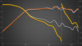
- After installing the crossovers in the boxes, measured the system FRD (same as above) then blended the responses in FRD Response Blender 2.0. - Plotted the simulated FRD and the measured FRD, see below.
The final result is obviously not that great, but for the cost (under 50 quid) and being his first attempt to DIY without cloning an existing design, he's happy with.
Question is, in the plot below, could the match between system FRD simulation and system FRD measurements considered as satisfactory? Blue and gray are measured values, orange and yellow are simulated values.
The purpose of this exercise was to check if his design procedure was sound, and if the simulation results match closely the measured results. Here's his design process:
- Routed the baffle and installed the drivers. Filled the boxes with some polyester wool.
- Measured the tweeter far field response (2mS window) and zma.
- Measured the woofer near field response (75mS window) and zma.
- Used the FRD Response Blender 2.0 spreadsheet to determine the minimum phase response for both drivers. The diffraction on the baffle edges was considered in this step.
- Used XSim to optimize the crossover values for an as much as possible flat system FRD and an as much as possible linear phase. Crossover frequency is about 3.5KHz.
- After installing the crossovers in the boxes, measured the system FRD (same as above) then blended the responses in FRD Response Blender 2.0. - Plotted the simulated FRD and the measured FRD, see below.
The final result is obviously not that great, but for the cost (under 50 quid) and being his first attempt to DIY without cloning an existing design, he's happy with.
Question is, in the plot below, could the match between system FRD simulation and system FRD measurements considered as satisfactory? Blue and gray are measured values, orange and yellow are simulated values.
Attachments
Hi, in my understanding the measured phase gray plot cannot be right, if there really is a higher-order crossover at 3.5KHz. From theory and simulation a phase shift is to be expected at this frequency. The blue plot looks o.k., tho one could possibly pimp it some. Have fun with Cheapo!
Hi, in my understanding the measured phase gray plot cannot be right, if there really is a higher-order crossover at 3.5KHz. From theory and simulation a phase shift is to be expected at this frequency. The blue plot looks o.k., tho one could possibly pimp it some. Have fun with Cheapo!
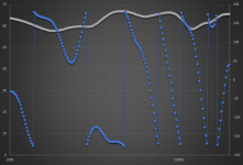
After measuring the tweeter far field and the woofer near field, the two responses were merged in FRD Response Blender, and the minimum phase response was extracted.
Extracting minimum phase from a finished 2-way speaker's response is almost certainly going to give you the wrong phase curves, as very few multiway speakers are actually minimum phase! You should only do that when you know that the response of the thing being measured really IS minimum phase (i.e., single driver, and a very few multiways).
And there is usually no good reason to do the extraction anyway, as most measurement systems (including OmniMic) measure true phase; why get a simulated curve when you already have a more accurate measured curve? Extracting minimum phase will actually give phase response errors even with minimum phase speakers. That's because noise limitations, bandwidth limits, and reflections that are in the measured magnitude response (which is all the extractor has to work with) will result in errors to the phase response. They usually aren't too significant, but they do happen.
If you extract minimum phase -- and are sure it is an appropriate thing to do -- you should always first clean up the response "tails" (regions where the measured magnitude response of the driver falls into the noise making it appear to level off or bump around) to make it continue to roll off as you're sure it should; and to provide the extrator data beyond the band edges (beyond 20kHz and below whatever lower frequency windowing has artificially limited valid data to). Phase extraction depends on data well beyond each frequency point it is extracting for.
If you only care about phase response in the crossover regions (well away from the measurement setup's limits, and where response is strong enough that noise isn't a problem), then the extracted phase is likely close enough to use for crossover design. But don't trust the results at the frequency extremes.
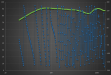
After measuring the tweeter far field and the woofer near field, the two responses were merged in FRD Response Blender, and the minimum phase response was extracted.
Good job. Not quite done - the next step is to add back delay. I do this using interference between pairs (or even all) drivers in the system. This info allows you to determine the relative offset in the time of flight for all the drivers in the system. You don't need to know the ACTUAL delay, only the RELATIVE delay with respect to the other drivers in the system.
I rely on the interference technique and find that it is very accurate - I can determine the relative offset to within a few millimeters. The reason for designing the Blender in the first place was to make it possible to blend nearfield and farfield measurements, but you can only recover the minimum phase from the blended frequency response. Therefore you need to do this extra step.
And there is usually no good reason to do the extraction anyway, as most measurement systems (including OmniMic) measure true phase; why get a simulated curve when you already have a more accurate measured curve?
I understand that the minimum phase is not the true phase, but I'm likely again missing something here. How can I get the true phase, in two different OmniMic measurements (tweeter far field, woofer near field)? If I click on "Show phase" I get nothing, and if I look in the exported frd files, the phase values are wildly jumping all over (see attached, far field response, window was 2mS, near field response, window was 75mS).
Attachments
Last edited:
Since you can't measure the true frequency response accurately for both high and low frequencies at the same time you have to make multiple measurements. How do you then combine amplitude and phase of these? I don't believe that you can because the mic will be in a different location for near- and far-field measurements and so the phase in each measurement will be very different. If you stick to 2-way speakers with crossover points around 2kHz you can "wing it" because this is where measured phase is very accurate in the far field. But below 1kHz things start getting dicey.And there is usually no good reason to do the extraction anyway, as most measurement systems (including OmniMic) measure true phase; why get a simulated curve when you already have a more accurate measured curve?
Since I dont see a way around that problem I now blend measurements and then correct the phase to reflect the relative phase difference between drivers, since that is really what you want to know for loudspeakers.
- Status
- This old topic is closed. If you want to reopen this topic, contact a moderator using the "Report Post" button.
- Home
- Loudspeakers
- Multi-Way
- Measuring speakers