Meanwhile OSCON SP 270uF/10V and BlackGate F 100uf/16V were added to my cap experiements, i also measured ESR at friend's rig. My conclusion so far is that esr and sound do not correlate directly in C15/C16 positions.
The measurements revealed that "audio grade" caps actually have pretty low ESR, at least at 13900Hz with Nichicon KZ almost as low as Pana FM, Silmic II slightly higher (but still a lot better than panasonic FC for example) and 15 years old BG F measuring lower ESR/D/Z than all of them except OSCON SP which had extremely low ESR (but sounded the worst)
As for sound - comparing these one after another my feeling is that caps are just "noisy" to a different degree. With OSCON being the dirtiest and thinnes sounding, while BG-F which is lowest in ESR after it - sound the oppisite - the "darkest" of the group, with least HF shril, harshness and grain. Then Silmic II, then Nichicon KZ, then Pana FM. Each have their own +\- in sound.
So far i decided to leave BG F in there so can get both - good measureable specs and sound without second thoughts")
I used Sanyo OSCON only for digital before to discover BG, I also prefer BG over Elna Silmic II
BIIIse dual mono 2 Legato output wiring
Hi,
in the final stage of building my case a few questions raise:
Wiring output anlog according the document for 2 ivyIII (http://www.twistedpearaudio.com/docs/digital/dualmono_BII_IVYIII.pdf)
Are the outputs on the Legato 3.1 sides labeld SE (on both sides of Legato Board) exactly the same as the outputs on the front of board labeld R/GND/L (normally used for HP)?
Therefore should i use the outputs on front of each Legato(with left/right flipped) for wiring my output with dual mono setup? It would be neater/shorter then using left and right side of boards together.
How and where do I trim out DC on Legato wired for dual mono?
Regards
Branko
Greetings Branko,
If I understand the question, you are asking to connect to the headphone out? If so, I don't think so as it goes through the op amps for normal single ended out. Fairly sure you must use the R and L SE out at sides of board.
You trim DC with the SE pots. Note; you will still be dealing with common mode DC, which is DC between pos balanced and ground, and neg balanced and ground. If your amp can't handle DC, you have to use coupling caps or lift (disconnect) the balanced ground. I run my balanced out with no ground (thinking the best coupling cap is no coupling cap). With dual mono, you'll see around 10 volts common mode DC versus 7-8v with single DAC board.
Just curious, why not run with a single Legato? I initially built my dual mono BIII using two Legatos, but changed to one. I didn't experience any loss of sound quality. Dual mono/one output board is covered in the BIII Integration Guide, page 69.
My photobucket dual mono BIII build.
Buffalo III Dual Mono Build by Rich Olszta | Photobucket
Rich
Hi,
in the final stage of building my case a few questions raise:
Wiring output anlog according the document for 2 ivyIII (http://www.twistedpearaudio.com/docs/digital/dualmono_BII_IVYIII.pdf)
Are the outputs on the Legato 3.1 sides labeld SE (on both sides of Legato Board) exactly the same as the outputs on the front of board labeld R/GND/L (normally used for HP)?
Therefore should i use the outputs on front of each Legato(with left/right flipped) for wiring my output with dual mono setup? It would be neater/shorter then using left and right side of boards together.
If I understand the question, you are asking to connect to the headphone out? If so, I don't think so as it goes through the op amps for normal single ended out. Fairly sure you must use the R and L SE out at sides of board.
How and where do I trim out DC on Legato wired for dual mono?
You trim DC with the SE pots. Note; you will still be dealing with common mode DC, which is DC between pos balanced and ground, and neg balanced and ground. If your amp can't handle DC, you have to use coupling caps or lift (disconnect) the balanced ground. I run my balanced out with no ground (thinking the best coupling cap is no coupling cap). With dual mono, you'll see around 10 volts common mode DC versus 7-8v with single DAC board.
Just curious, why not run with a single Legato? I initially built my dual mono BIII using two Legatos, but changed to one. I didn't experience any loss of sound quality. Dual mono/one output board is covered in the BIII Integration Guide, page 69.
My photobucket dual mono BIII build.
Buffalo III Dual Mono Build by Rich Olszta | Photobucket
Rich
Last edited:
Greetings,
thank for helping out.
Just wanted to use two legato because I have two
thought it would be true dual mono this way. I have build a dual monad BII with two ivyIII with great result.
But with two legato I do not get it right. Both BIIIse are working well. And simple stereo via balacrend outputs work with both legato too.
But if I go dual mono sound is ugly compressed an kind out of phase? Tripe checked wiring. any clue?
Btw: for two BII and 1 Legato would it be better to power right/left half of this legato with separate PlacidBP HD ?
regards
Branko
Two it is then!
Have you tried each Legato separately? If they both work in stereo I don't see them affecting sound in a bad way dual mono. Are you using Arduino or manual control?
Because I had two Legatos, I use the second power supply to power left channel and single ended/headphone out. I can't say I hear a difference with two power supplies, but they run cooler as I don't have to shunt them as high.
Hi,
will try it today with 2 BIIse and 1 Legato.
One question wiring the output with one legato: I followed the integration guide p. 69 for connecting the BIIse to legato. But do I have to switch + and i on right to left channel. Or should I use the same on booth outputs.
thx
Branko
will try it today with 2 BIIse and 1 Legato.
One question wiring the output with one legato: I followed the integration guide p. 69 for connecting the BIIse to legato. But do I have to switch + and i on right to left channel. Or should I use the same on booth outputs.
thx
Branko
Hi,
will try it today with 2 BIIse and 1 Legato.
One question wiring the output with one legato: I followed the integration guide p. 69 for connecting the BIIse to legato. But do I have to switch + and i on right to left channel. Or should I use the same on booth outputs.
thx
Branko
The only crossing takes place in relation to wiring the DAC boards to Legato inputs. Dual mono and antiphase IIRC.
Follow proper polarity with R and L balanced and SE outputs. The output isn't that high on the Legato...skim down to bottom of page 70. If your output is too high, put a 300 Ohm resistor between + and - balanced. It will give you ~ 6dB reduction.
Page 27 for dip switch settings. If using Arduino / HiFiDuino code, you make those selections in the beginning of the code.
Last edited:
Thank you again for kind support in this forum )
Got it up and running today
Listening to sweet music all the Afternoon.
Next step is to put together input selection and display.
Will use a 4:1Mux/receiver to I2S to Otto side B1 and Teleporter (from Amanero/cronus) to B2 side of Otto (BTW if someone has working hifiduno code for this input-selection please share it with me) Coding, even arduino is not my thing.
For display i will use a small (1.9mm per dot) matrix display i made (8x48 dots). It only needs I2C and power connection and works with adafruit arduino libraries,
It is ultra bright an readable from distance even to older eyes. I want it to show only few informations like input source (i.e. Mac; CD; TV) and sampling rate or volume level.
A lot left for now. but I am on the way.
)Got it up and running today
Listening to sweet music all the Afternoon.
Next step is to put together input selection and display.
Will use a 4:1Mux/receiver to I2S to Otto side B1 and Teleporter (from Amanero/cronus) to B2 side of Otto (BTW if someone has working hifiduno code for this input-selection please share it with me) Coding, even arduino is not my thing.
For display i will use a small (1.9mm per dot) matrix display i made (8x48 dots). It only needs I2C and power connection and works with adafruit arduino libraries,
It is ultra bright an readable from distance even to older eyes. I want it to show only few informations like input source (i.e. Mac; CD; TV) and sampling rate or volume level.
A lot left for now. but I am on the way.
Glad to hear it! (Pun intended...lol)
The code! The code!
I'm code challenged myself. Two places to get code that I know of, HiFiDuino whom initially wrote it and CE Designs who modified it to fit his Buffalo shield design (CE328 firmware). CE Designs also used an I2C LCD extra IO board so the code is most likely modified for that. I recall having to add a special library and the address of the IO card had to be designated at start of code.
Also, both sets of code are for 20×4 LCD. IIRC the code has to be changed IF the display size and type is changed.
Someone should correct me if I am wrong, but I think you are going to have to modify code for your application. You can try the code without the Arduino connected to the DAC and see if it works.
https://hifiduino.wordpress.com/introduction-and-guide-to-hifiduino/
CE328 Firmware
EDIT: There was a fellow here ?dimdim? that used a large touch screen display with HiFiDuino code? He has some solid code experience.
Last edited:
I already did search for software variants to reach my goal.
I also looked at Ce644 and DimDim code. These are way to complex for me.
So i will go with basic hifiduino. In the twisted pear support forum is a hint how to implement inputselection with 4:1 mix and otto. Have to try this.
As for the Display i have some success already too. As it is I2C I can "dasychain" it with a typical 4x20 LCD an only have to make minor code changes (add printLED ... after the printLCD ... instruction). So i can only let the LED-Martix display the things i would like to see. The other Information is only needed for initial setup. After that I can always connect a cheap 4x20 LCD (with I2C adapter) to the I2C bus (have a spare 4pin connector on my LED-Matrix with SDA/SCL/5V/GND) and make changes. I could even have it left inside the (at moment nonexistent case). The approach i use to the code for the LED-Display is far from "elegant" but works somehow. I have made a PCB with OSH an it is shared to everyone who wants to get one from OSH at reasonable price. I will try to post some pictures tomorrow. It si late her in germany and workday is coming near
I think it would be worth for someone with skills to make better code for this type of display.
Some question about grounding it all.
With my dual mono BIIIse / one Legato I use 2 placid HD for BIIIse and 1 Placids HD BP for legato.
For 1x Teleporter, 1x Otto II, 1x 4:1 Mux/Receiver and 1x Toslink Modul I don't know: would it be better to use a separate supply? Or use the two Placids already there?
Should I use some kind of "Star"-groundig?
Should case Ground and other ground be connected? (and how)
Sorry for these lot of questions. But It seems with each step forward more questions appear.
Regards
Branko
No worries about questions, ask away.
I used TP linear power supplies for Arduino (12v) and modules (5v). You can use the Placid's for the modules provided they have enough heat sink for the added heat. Them milliamps add up!
Post 15 in link below, Russ suggested I star ground all my modules and power supplies. I used a ring terminal and soldered grounds to it. The DAC power grounds, Legato power grounds, PS grounds and all module power supply grounds all connect at the star ground.
Buffalo III *now* Dual Mono Build / Denon DVD-3910 Mod
No to connecting the PS/module grounds to the chassis ground. I used a nylon standoff to secure the star ground after the ring terminal cooled off. You can just see the star ground in this pic between the left DAC and linear power supply. This pic was before I went single Legato. I kept the two Placids and power the left/single ended and right channels of the Legato. (I left the J1 and J2 jumpers in, and removed the J3 and J4 jumpers on the Legato). I did attach chassis ground to IEC power connector ground. You can see it next to linear supply with female spade, it attaches to transformer angle which attaches to chassis floor.

Last edited:
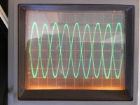
Comparing playback volumes between my old Legato 2 and current Legato3.1, the newer board is quieter. Both have 680/150 ohm resistors. On some tracks I could really use more output from the new boards. I ran a 440Hz sine wave from the BBB at -0dB and got the below trace (0.2 v/div). 1.2 volts max. For my current listening room I think I could use a full 2 volts at -0 dB. The Legato info doc suggests that 187 ohm lower resistors will produce that, but I'm doubtful if 150 ohms gives only 1.2v.
Comments or suggestions? TIA!
Frank
Comments or suggestions? TIA!
Frank
Attachments
my results...
I have 187R upper resistors and (if I remember correctly) 820R (with two in parallel) lower resistors and I get almost exactly 2 volts output at 0 dB. No noise problems either.
Comparing playback volumes between my old Legato 2 and current Legato3.1, the newer board is quieter. Both have 680/150 ohm resistors. On some tracks I could really use more output from the new boards. I ran a 440Hz sine wave from the BBB at -0dB and got the below trace (0.2 v/div). 1.2 volts max. For my current listening room I think I could use a full 2 volts at -0 dB. The Legato info doc suggests that 187 ohm lower resistors will produce that, but I'm doubtful if 150 ohms gives only 1.2v.
Comments or suggestions? TIA!
Frank
I have 187R upper resistors and (if I remember correctly) 820R (with two in parallel) lower resistors and I get almost exactly 2 volts output at 0 dB. No noise problems either.
I have 187R upper resistors and (if I remember correctly) 820R (with two in parallel) lower resistors and I get almost exactly 2 volts output at 0 dB. No noise problems either.
Thanks for the data point! I have decided on 195/847. I'll use paired 1/2 w resistors from PRP (which sounded great in the Legato 2). Cheers!
I have 187R upper resistors and (if I remember correctly) 820R (with two in parallel) lower resistors and I get almost exactly 2 volts output at 0 dB. No noise problems either.
I have made final output tweaks to my 3 Legatos and the good news is that they sound wonderful and their outputs now help compensate for different driver efficiencies. There is no audible noise and sound levels are adequate on quieter recordings. So, mission accomplished.
However, when I measure the output I’m still unsure what is going on. This is what I have observed from a 0dB sine wave produced via SoX on the BBB:
150/681 ohm - 1.2 v/differential channel
165/750 ohm - ~1.3 v/differential channel
180/820 ohm - 1.5 v/differential channel (~3v SE)
195/848 ohm - 1.6 v/differential channel
I was expecting 2 volts with the 195/848 ohm pair! Any thoughts about what is (apparently) limiting the output? What am I missing?
B3 I2C registers 1-8 are at 0 and registers 20-23 are maxed. There is no amplitude difference between filtering the signal in ALSA and sending it to hw:0,0 in the BBB. I just wonder if the B3 is performing differently with output from BBB/Cronus than it would with a different I2S source.One observation re the resistors - compared to the stock Vishays (very good indeed) the red PR9372s are at least equal. I think I’m hearing even more recording environment acoustics now compared to before the resistor swap.
Cheers,
Frank
Using only Balsie
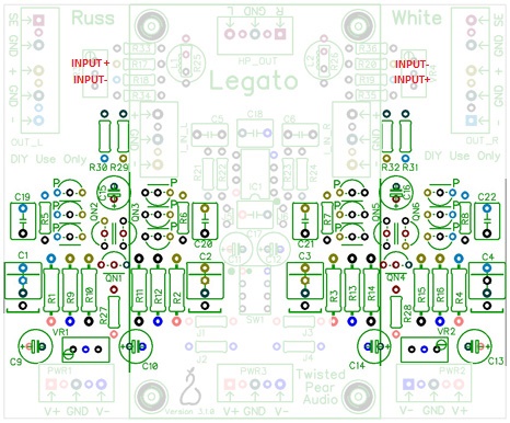
I want to use only the Balsie to convert balanced signal to unbalanced signal, looking at the schematics I guees I have to disconnect one leg of resistor R17 input+ & R18 input- for left channel & R19 input+ & R20 input- for right channel, it's OK?
TIA
Felipe
I want to use only the Balsie to convert balanced signal to unbalanced signal, looking at the schematics I guees I have to disconnect one leg of resistor R17 input+ & R18 input- for left channel & R19 input+ & R20 input- for right channel, it's OK?
TIA
Felipe
I want to use only the Balsie to convert balanced signal to unbalanced signal, looking at the schematics I guees I have to disconnect one leg of resistor R17 input+ & R18 input- for left channel & R19 input+ & R20 input- for right channel, it's OK?
Yes.
150/681 ohm - 1.2 v/differential channel
165/750 ohm - ~1.3 v/differential channel
180/820 ohm - 1.5 v/differential channel (~3v SE)
195/848 ohm - 1.6 v/differential channel
I was expecting 2 volts with the 195/848 ohm pair!
Cheers,
Frank
Your results are pretty close to what I would expect - not to fear.
You could go 221/848 and the circuit should work fine, but if you have high enough level output I would just leave it alone.
- Status
- This old topic is closed. If you want to reopen this topic, contact a moderator using the "Report Post" button.
- Home
- More Vendors...
- Twisted Pear
- Legato 3 - Look ma! No caps!