I2S is a digital protocol or a standard way to send digital steams into a digital system, between two processing stages. This is used most for digital audio.
For more detailed informations about, you may just google on I2S...
In this case of this sound card. I2S protocol (lines) is used as interface between the audio processor on board, and the DAC chip. The audio processor on Asus sound card it get its informations (digital stream) through another protocol/standard interface - PCI or PCIex, from the main computer processor or so. The DAC chip it get the digital informations to be converted into audio signals, through its input I2S lines (4 lines for digital informations).
This interface is very efficient and safe, but is very sensitive to long traces/distances. Distances of more than few cm PCB traces it can alter the information. There is no way to use wires for such connection, but only carefully designed traces on a PCB.
In my approach (previous picture) I use a special designed flexible PCB to connect my DAC board inputs to the Asus board (through galvanic isolators).
Last edited:
hi everyone!
i'm new in this forum and i'm from italy, sorry for my errors language...
i hope someone can help me with my question:
i have asus xonar ST with multich card H6 that i use in my htpc for movies, multichannel music and 2ch....
the card it's modded and it works only with external power linear supply that provides current to the ST for all -12V + 12v + 5v + 3.3V
and for each line there are a + and a -
my idea is to provide direct current also to the h6, the same that i have now for the ST card.
i have found this layout of the 25 pin input of the H6 but i dont know if it's correct or not!
if i follow this can i only connect the positive lines from the external psu directly to the H6 input? is it correct?
or should I do differently and how?
i dont see -5 or -3,3
thanks....
Attachments
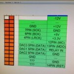
I do not think it may be any of -5v and -3,3v involved there... I suppose the extension device H6 it should be powered from the main board/card, through its interface...
The power rail -12v it is necessary only for the post DAC analogue processing (opamps). The rest of the power rails are computer standard (+12v, +5v, +3,3v)
The power rail -12v it is necessary only for the post DAC analogue processing (opamps). The rest of the power rails are computer standard (+12v, +5v, +3,3v)
Last edited:

Well, this is a piece of art, I can say...
Only lot of work in itself to remove the almost all components on the original board, without damaging too much the original PCB... This is a really performance! However, I`m quite sceptic about the repeatability of this performance...
A tremendous work to redesign all in a quite complexe (much more complex) approach, especially about the clock system.
Very good measurements results.
For sure a very expensive project and finally a proportional expensive modified sound card...
At least we have now a mod version more, and a very professional one too. Nice if the author could joining here...
I mentioned in one of my previous posts (745), about my (very) final mod version for ST/STX sound cards.
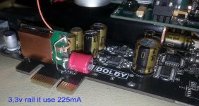
Well, I found out about a very important detail, which I have ignored it until now: the 3,3v rail for the digital stage on board. This power rail is coming from the computer motherboard (through PCIe connector for STX board). There is a quite big ferrite bead which is used as filter on this power rail (picture).
I disconnected this rail from the computer power system, and I used one of my ultra low noise 3,3v regulators (based on ADM7151), to power the digital stage of the sound card (I used also for this purpose, one of the power rails in my dedicated PSU for the system). Please note that this 3,3v rail is a digital one, and it must have as GND the digital ground on the board/computer (in my case completely isolated from the analogue one). The result: exceptional, and over all expectations. I never imagined the digital chips involved in this sound card design and processing, are capable for such fidelity, and very high quality for the outputted audio signals. They are indeed, when it get the right very low noise power.
To power the processors on board by a low noise (analogue) power supply it is the same crucial as doing it for the DAC chip, and the post DAC analogue signal processing circuits.
The dynamics of the signals are improved a lot, the soundstage, and the fidelity of the reproduced sound components it is only unprecedented. The bass components are very powerful (at the same volume level), deep and very pleasant to listen to. The volume of the soundscene is larger and the sound elements very well defined as positions. The overall impression: extreme fidelity.
Attachments
Last edited:
Well, all the informations are already in the pictures I published in my previous post. However, without knowing some basics in this field, may be quite difficult to fulfil the task...
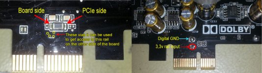
The eventual 3,3v regulator it should be placed so to input its power in the point marked on the picture (vias), and the ground connection could be right beside (creating a GND point by scratching the ground plane of the board in that area).
An external power supply for this board, should be ON/OFF synchronized with the main power system of the host computer.
Attachments
I forgot a detail about the 3,3v rail. The power supply or regulator for this rail should start up (power up) quite fast, together with the rest of the system. Else the processors on board may not communicate with the computer (BIOS initialization) in the right time, and the sound card may fail to identify itself, or it will not be recognized by the system...
This rail is coming from the main computer PSU, via motherboard/PCIe connector, and it does not have any regulation on sound card. Straight to the chips. Some ferrite beads and caps are meant to filter out the noises...
The rail it goes to the digital stage on the card and it power the digital part of the (on board) DAC chip, through another ferrite bead.
The rail it goes to the digital stage on the card and it power the digital part of the (on board) DAC chip, through another ferrite bead.
Hi Chris, this mode is applicable to pci version as well, I imagine. Could you be so kind to indicate me a good PS for 3.3 line?This rail is coming from the main computer PSU, via motherboard/PCIe connector, and it does not have any regulation on sound card. Straight to the chips. Some ferrite beads and caps are meant to filter out the noises...
The rail it goes to the digital stage on the card and it power the digital part of the (on board) DAC chip, through another ferrite bead.
Thanks
Thank you very much Coris!!! In your opinion I will have better results powering the DAC with a separate power supply or adding on 3.3v line a belleson regulator mk ii 225mA?Hi oct81
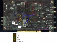
I found this picture long time ago. Maybe it will help you (and others)...
The DAC chip it is powered with both 5v and 3,3v. Also the post DAC analogue signal processing (I/V and final buffer) should be powered by a better power supply, than it is on the original board.
As you maybe have seen, my own mod approach is to entirely power the DAC and post DAC circuits from a completely separate PSU. Then isolate the digital interface to cut any electrical connection/contact with the rest of the computer. This approach it have a huge positive impact over the analogue signal quality.
Also the rest of the digital chips on the board are powered by 3,3v, which is (original approach) taken from the computer 3,3v main power rail.
I have cut it that main 3,3v rail to the board, and used an low noise regulator to power the board digital stage with this voltage. My low noise regulator it use a analogue power stage, which is independent from computer. These power mods it improve dramatically the sound quality, the dynamics, fidelity, etc.
Important to mention here is that the power up/down sequences of the sound card system (its own power system/PSU), should be synchronised with the computer power up/down sequences.
As you can see in my previous posts, I have already designed a such external power system (synchro included). I have now available its last version, which it include an extra regulator for 3,3v rail of the digital stage on board... My power board provide +/- rails, for post DAC signal processing, as one 7-9v rail which may be used to power the DAC chip (regulated down to 5v and 3,3v).
Actually I may have available the whole/complete kit (DAC system), as you can see in my previous published here pictures...
- Home
- Source & Line
- PC Based
- Xonar ST/STX mods...