I have read a few threads on here where people have had good experience operating the IXYS CCS's with 1-5mA and some below 1mA.
I've used them in low current situations for years and they do work well. Recently I got the urge to try a BJT CCSink similar to ones shown in Morgan Jones under some LTPs that operate at under 10mA. While the IXYS cascode CCSs work well here, the BJT CCSs smoked them sonically. Less apparent distortion, more soundstage depth, more cleanly enunciated sibilants, etc. Not a subtle difference. Of course your milage will vary. I was able to use high hFE RF transistors (BC549C, low capacitance). As a plate load you will require PNP transistors and probably more voltage rating for the upper device. That will cost some performance, but could still outperform an IXYS cascode. Remember the AC impedance of a BJT CCS is equal approximately to the value of Rset times the hFE of each transistor. With an hFE in the range of 600 to 800 the AC impedance of a BC549C cascode and an Rset on the order of 500R is quite large. The low capacitance helps maintain that impedance at higher frequencies. Data from Walt Jung's study of CCSs published in AudioXpress show that the power MOSFET CCS AC impedance starts to fall off at 6dB/octave above ~500-1K kHz due to devise capacitance.
The valve bias voltage has more effect on its distortion than the LED nonlinearity. Feeding extra current to the LED increases the bias slightly, which actually worsens the distortion (albeit a teeny tiny amount).No real difference over a resistor only.....?
Then your problem is solved! Use an unbypassed cathode resistor. This significantly lowers distortion while having negligible effect on gain, assuming no heavy external load.The whole reason I am looking at the CCS and LED is lower distortion, PSU noise reflection, and the sound of an unbypassed cathode with the gain of a bypassed cathode.
EDIT:
I have not found this to be the case, and I have difficulty seeing how it could?A cathode resistor, unbypassed, increases the distortion when a CCS load is used.
I have not found this to be the case, and I have difficulty seeing how it could?
This surprised me as well, but it's a measurement I repeated a few times. I don't know why it should be the case, on the face of it, it shouldn't matter much. I would love to have the time to investigate this.
A cathode resistor, unbypassed, increases the distortion when a CCS load is used.
Compared to what? Not clear what 2 topologies you are comparing. Unbypassed cathode R + anode CCS vs ? + ? And what's held equal between the 2 cases? Current? Stage gain? Vg? I'm also surprised and I'd like to try and duplicate that result. Perhaps you could post the actual 2 circuits you compared.
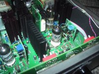
Here's a photo of two BJT CCS in my phono pre. I mounted them on the existing MOSFET cascodes. They don't require much more room.
Well I would have to mount them horizontally on a vertical board in a 1U rack pre. A have about the room of a quarter for each one. I could probably get a pcb that dmall, but it would be tight.
I'm using a MOSFET cascode (IXYS 8N50D2/1N100D) plate load on the 6SN7 input stage of my 2A3 SET amp @4.5mA and they sound great. I'd probably wait and try the BJT later after everything was sorted out if you are curious. I do suggest using the IXYS 8N50D2 on the bottom of the cascode, it's a significant improvement over either the 1N100D or the 8N100D2 in that position. Also do not mount the two MOSFETs on the same heat sink. The added drain to drain capacitance (~10pF) is not wanted.
A cathode resistor, unbypassed, increases the distortion when a CCS load is used.
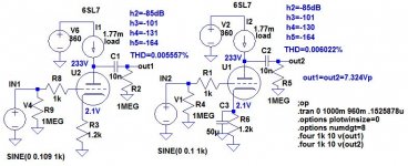
Sim says otherwise, by a small amount. I'd be interested if you just observed this in one particular circuit or if you base that statement on a more extensive set of tests/observations.
Attachments
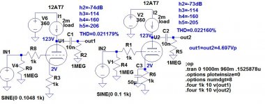
One circuit, 12AT7 at 2mA, 2V bias. But I ran it a couple of times because I didn't believe the results.
Simulation shows again the expected results. Unbypassed cathode version lower distortion. In my humble opinion something not kosher in the circuit you measured, or something peculiar about the tube used. I don't have a good setup for measuring THD accurately, perhaps someone else can try breadboarding this simple stage and confirm results.
Attachments
Last edited:
I am pretty new to electronic design.
Yes.
Would a well regulated supply across a plate resistor not act like a CCS?
No. Any well regulated supply will have a very low impedance. That's why it provides a constant voltage into varying loads. It would "short out" the plate load, and there would be no meaningful output and loads of distortion.
I understand that as the resistor heats up, its resistance value changes, hence so does the current across it. But, wouldn't this eventually stabilize, or is the voltage swing across the grid force enough variation in current accross the plate resistor that it can not longer be considered constant?
For small signal applications, this is of no consequence.
How much difference in (audible) linearity would there be between a CCS and a well regulated B+?
Two different issues. An active plate load (CCS) will give the best linearity if it looks into a Hi-Z load. For low distortion audio, this is what you usually want. It's especially important when working with triodes, as triodes produce the lowest distortions with light plate loading. That's long been the big problem with the 12AX7: its nominal rp= 90K -- small signal pentode territory. There are all too many designs where the plate loading is excessive, and therefore the complaints about the 12AX7's inferior sonic performance. You'd like a load of 180K or better, but you'll also need the VPP to allow for the resulting voltage drop. Plate load resistors are often too small. It's also why the 6SL7 is thought to be the better dual triode: the u-factor is lower, but so is the rp= 44K, so it's easier to install a large enough plate resistor for good linearity.
Back in "the day" it was a problem. These days, you can use a SS active plate load to avoid the voltage issue. The sonic performance becomes excellent.
As for sonic performance, that depends. I don't like active collector loads on the first LTP of a SS amp to make it do double duty as a 1st pre and a VAS. Keep these functions separate. Active collector load(s) on the VAS are OK, and pretty much mandatory to get the open loop gain needed to support the gNFB a SS amp needs to sound good.
As for stabilizing the DC rail, this isn't such an issue with pentodes in PP. For SE triodes, it will help since triodes are sensitive to VPK much more than pentodes and transistors. Voltage regulation is more likely to be desirable for music reproduction than for production. Many guitar amps are designed with poor voltage regulation on purpose as this gives "sustain" as the note fades and the plate voltage comes back up.
No, I was talking about a bypass resistor to feed extra current to the LED. The bare LED works fine as-is. A cathode resistor, unbypassed, increases the distortion when a CCS load is used.
This scenario was tested back in the '50's. The results were inconclusive regarding sonic performance. This becomes a case of try and listen.
If I wanted the utmost in cleanliness in a bass guitar amp, I wouldn't bother with voltage regulation, although I'd have some pretty significant double RC filtering in the power supply, and I might bother with putting a CCS on the plate of the 1st stage tube, mostly for power supply rejection (of hum), but frankly I doubt if this is going to make much difference for a bass guitar. I'd worry instead about making sure to run the tubes at their optimum quiescent current (get all the tube graphs, not just the one), and then there's crossover and blocking distortion in any push-pull output stage that can be pretty bad if it's ever over driven. And then the speakers themselves. Hard cone drivers, such as kevlar, will sound cleaner, and it's especially noticeable when you play 2 strings together, forming a simple chord, because they will try to generate sidebands, otherwise known as intermodulation distortion products, which to some extent can be a plus, but can be over done real easily. The difference product can give the sound a slight vibrato effect, which can be fun, but I'm not sure what the best way to do that would be with bass guitar.
For a bass amp, the output transformer is quite possibly the weak link. It needs to have a rather large core, compared with regular guitar amps. I built a hi-fi tube amp using Hammond xfmrs, and found that the distortion went up dramatically below about 70HZ... and the specs suggested that the core would be big enough. Since I'm using it in a tri-amp'd speaker arrangement and it doesn't handle any bass freqs., I haven't bothered to fix that issue. But it was a valuable learning experience.
For a bass amp, the output transformer is quite possibly the weak link. It needs to have a rather large core, compared with regular guitar amps. I built a hi-fi tube amp using Hammond xfmrs, and found that the distortion went up dramatically below about 70HZ... and the specs suggested that the core would be big enough. Since I'm using it in a tri-amp'd speaker arrangement and it doesn't handle any bass freqs., I haven't bothered to fix that issue. But it was a valuable learning experience.
They had LEDs in the 50s? Citation??This scenario was tested back in the '50's.
They had LEDs in the 50s? Citation??
Technically, they had LEDs in 1902, but that's a whole 'nother story.
You didn't comprehend. What Sy was discussing was bypassing the cathode resistor of a CCS loaded triode. Some said that this resistor didn't need bypassing as the current was constant, therefore no AC across the cathode resistor, so no need to bypass it. Others disagreed. So in the '50's this was put to the test. As with most things involving perceived sonic performance, the test was inconclusive. Some preferred the performance with bypassed cathode resistors, others liked it without.
Nothing to do with LEDs here, other than LED bias would essentially be the same as cathode resistor bias with a large bypass capacitor.
- Status
- This old topic is closed. If you want to reopen this topic, contact a moderator using the "Report Post" button.
- Home
- Amplifiers
- Tubes / Valves
- Can regulated B+ act like a CCS?