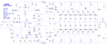
I simulated this amplifier in LTSpice and is working very good. It has a basic and simple schematic. I was inspired from several schematics, but mainly from Bob Cordell book. You have the schematic and simulation results in the attached archive.
I have many questions but first of all I want to ask you what transistor should I chose. I prefer SMD where is possible. I wrote on the schematic the Vce, Ic and Pd needed for each transistor. The output stage I think it's ok. But I'm not sure about the other transistors. For example... Q1, Q2 (2SA1312) they have 150mW Pd, but in this schematics they dissipate 90mW. Is it to much ? They will heat up to much ?
I'm not sure for Q4, Q11, Q14 too. Is it some other transistors better for this ?
Attachments
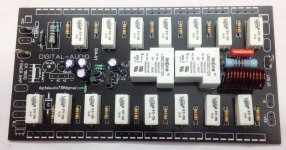
Hi andrewlebon ,can you share all files from this amplifier?Maybe this can help you i am trying it my output pcb")
No one knows to answer my question ?
According the datasheet, you can dissipated 90mW below 60 degree celcius of ambient temperature.
Marus - I have a personal policy to never download or open up ZIP files. The number of viral parasites that hitch a ride on ZIP files is amazing. There may be other silent readers who have the same policy.
I propose that you post good screen-resolution captures instead. We're pretty competent at opening them, gazing at them, then commenting. And there are no zip files involved.
I wish you luck in posting the direct graphics.
GoatGuy
I propose that you post good screen-resolution captures instead. We're pretty competent at opening them, gazing at them, then commenting. And there are no zip files involved.
I wish you luck in posting the direct graphics.
GoatGuy
Ok, sorry. I didn't know. Here is the content of zip archive:
Attachments
-
 THD vs Freq.png8 KB · Views: 132
 -
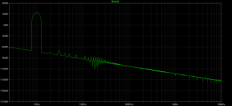 THD 0.0008% @ 1KHz 800W.png14.9 KB · Views: 132
 -
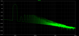 THD 0.01% @ 10KHz 800W .png17.3 KB · Views: 122
 -
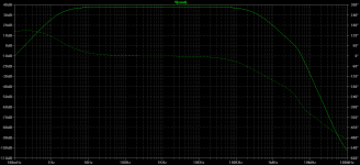 band.png17.6 KB · Views: 594
 -
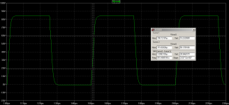 slew rate.png18.2 KB · Views: 616
 -
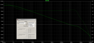 phase margin.png26.8 KB · Views: 672
 -
 Schematics.png102.1 KB · Views: 743
 -
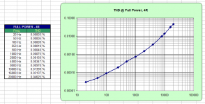
 THD vs Power.png6.9 KB · Views: 128
Your output design is very similar to Ostripper's Slewmaster series. The output devices you have chosen have been found to be too slow for the EF3 design and can oscillate and self destruct. His bias spreader is worth looking at too.
http://www.diyaudio.com/forums/solid-state/248105-slewmaster-cfa-vs-vfa-rumble.html
http://www.diyaudio.com/forums/solid-state/248105-slewmaster-cfa-vs-vfa-rumble.html
If I recall correctly, the reason they were failing was because slow output devices don't shut off fast enough and can suffer from shoot through. Ostripper was recommending 30mHZ minimum.
I used Sanken 2SA1295/2SC3264. Ostripper and I both found these run cooler. Your NLW1302/3281 were popular for his designs too.
I used Sanken 2SA1295/2SC3264. Ostripper and I both found these run cooler. Your NLW1302/3281 were popular for his designs too.
Exactly,i have smoke some slow devices using them as output in slewmaster.Your output design is very similar to Ostripper's Slewmaster series. The output devices you have chosen have been found to be too slow for the EF3 design and can oscillate and self destruct. His bias spreader is worth looking at too.
http://www.diyaudio.com/forums/solid-state/248105-slewmaster-cfa-vs-vfa-rumble.html
I got the lesson...slow amplifier slow transistors,fast amplifier(EF3)fast transistors.
Hi Guys
It is not universal that you must use the fastest devices to attain very high speed or bandwidth when it comes to an audio power amp - even one with +/-90 or 100V rails. Given that it is an AUDIO application, there is a certain need for rise-time, slew rate and bandwidth, and having too much more is generally problematic.Using the MJL21193/4 pair often improves stability and distortion, but it depends on the design. Some people have a skill for blowing up almost anything.
The OPs's circuit could be improved if the current source facing the TIS/VAS had its own control transistor. The thrift that saves 25-cents on the BJT and extra Rs and Cs also sacrifices speed in this stage. Countering this, the "speed up" cap often used across the base-to-base leaks in the driver and output stages does not always improve things.
Most power amps are essentially the same circuit copied and pasted, with voltages increased, more output devices added. extra drive stages added, more voltage gain added if required - so to say that following such a development process is the wrong way to do it itself incorrect.
Have fun
Thank you guys, it seems that you are right.
I have checked in simulation the collector current of power devices, when they are driven in clipping, and indeed they make a little cross conduction.
If I add a 3,3uF speed up cap the things are getting better, but not perfectly:
If I change the output devices with NJW3281 (30MHz) there is no cross conduction at all.
But unfortunately, I must make this amplifier with those MJW21196's because I already have them. And because NJW3281 doesn't have enough SOA for this power and those Sanken devices recommended by jwilhelm they are not easy to find...
Do you think it's ok with that speed up cap or I should change the output stage configuration for my 4MHz devices ?
I have checked in simulation the collector current of power devices, when they are driven in clipping, and indeed they make a little cross conduction.
An externally hosted image should be here but it was not working when we last tested it.
If I add a 3,3uF speed up cap the things are getting better, but not perfectly:
An externally hosted image should be here but it was not working when we last tested it.
If I change the output devices with NJW3281 (30MHz) there is no cross conduction at all.
But unfortunately, I must make this amplifier with those MJW21196's because I already have them. And because NJW3281 doesn't have enough SOA for this power and those Sanken devices recommended by jwilhelm they are not easy to find...
Do you think it's ok with that speed up cap or I should change the output stage configuration for my 4MHz devices ?
- Status
- This old topic is closed. If you want to reopen this topic, contact a moderator using the "Report Post" button.
- Home
- Amplifiers
- Solid State
- 800W Power Amplifier