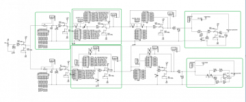
I would recommend separating the EQ and "effects" from the crossover.
A crossover PCB separate from the EQ & effects PCB will make each PCB much simpler and save having to throw away good parts when something is changed.
I agree with Andrew.
I would recommend separating the EQ and "effects" from the crossover.
A crossover PCB separate from the EQ & effects PCB will make each PCB much simpler and save having to throw away good parts when something is changed.
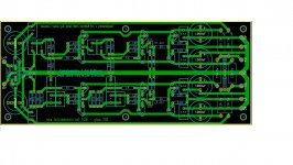
Green areas I believe = separate pcbs !!!
Attachments
I'd still like to see the pcb happen.
I'm currently reevaluating the configuration of the XO. What's you guys' opinion on the following:
- BSC followed by another buffer AFTER the low pass
- Output level control followed by another buffer AFTER the high pass
That way we should end up with better S/N ratio, no? And since tweeters (or midrange in 3 way systems) are generally more sensitive than woofers, only the HP branch needs a relative level control, no?
I suppose (?) AndrewT was suggesting such a configuration in these posts.
Hi expert's
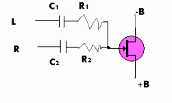
Build this active crossover B1 scheme and its fun
I have 2 FR speakers, 100Hz cutoff 2 woofer, I want to build only one LF and one amplifier to the woofers.
What is the best way to mix the signal in this B1?
Another Q: the first stage can feed all the filter (HPr,HPl,LP) ?
thanks
Build this active crossover B1 scheme and its fun
I have 2 FR speakers, 100Hz cutoff 2 woofer, I want to build only one LF and one amplifier to the woofers.
What is the best way to mix the signal in this B1?
Another Q: the first stage can feed all the filter (HPr,HPl,LP) ?
thanks
Attachments
The modified tapping point to preserve the HF roll off slope has not been incorporated.
The input Buffer (the first two K170 on the extreme left) is designed to drive the next filtering stages. The Idss of the K170 will determine how many stages can be driven.
The lower Gr grade may be suitable for two filter stages. The Bl grade should easily drive three or more stages. Note each capacitor that follows the Buffer has a 10k2 resistor in series. That makes the filter stage an easy load. All the filter needs is a lowish source impedance to achieve the predicted frequency cut off and Q
If you know your driver sensitivities, you can predict which channel (Hi Pas or Lo Pass) needs a bit of attenuation. It is extremely unlikely that both channels need an attenuation adjustment. In general the higher sensitivity Driver is the treble and this is the one that needs the adjuster and Buffer. The lower sensitivity driver can omit the extra adjuster and omit the Buffer that follows.
Consider whether any input and/or output DC blocking capacitors may give some peace of mind.
Last edited:
For mono you should really be using a summing stage.
The signal out of the summing stage is the SUM of the two input signals when the two signals are in phase.
At LF the signals are supposed to be in phase, thus you can expect the LF summing stage output to be twice the filtered single stereo signal.
The signal out of the summing stage is the SUM of the two input signals when the two signals are in phase.
At LF the signals are supposed to be in phase, thus you can expect the LF summing stage output to be twice the filtered single stereo signal.
twice is good for open baffle woofer.
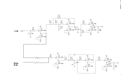
what about the next scheme, the fet is the first stage from the filter scheme,
just mix the channel with R1,R2.
do i need capacitor?
what about the 220 ohm and 22k from the filter scheme, remove them?
I don’t want the signal back to the stereo signal
what about the next scheme, the fet is the first stage from the filter scheme,
just mix the channel with R1,R2.
do i need capacitor?
what about the 220 ohm and 22k from the filter scheme, remove them?
I don’t want the signal back to the stereo signal
Attachments
The resistor method (passive) is not as good as the summing stage (active).
But worth trying. It may be good enough.
Add a gate resistor at the gate.
You can delete the two capacitors.
The two stereo Buffers feed the two input resistors.
An excellent summing and filter stage is the MFB. It uses just one active stage to both sum and filter a 2pole roll -off. The MFB needs an amplifier, not a Buffer. So start with a FET input opamp. opa134 is good enough. It will run from the same supply rails as the B1
Last edited:
Oh, I forgot the Buffer for the modified tapping point, well done.
If the LoPass is 106Hz, that makes the other half 106Hz as well. That is upper bass and mid and treble.
Try somwehere from 10k to 47k for the passive mixing to mono.
Note, you are using 6 high value k170 to replace one opa134.
If the LoPass is 106Hz, that makes the other half 106Hz as well. That is upper bass and mid and treble.
Try somwehere from 10k to 47k for the passive mixing to mono.
Note, you are using 6 high value k170 to replace one opa134.
Last edited:
Oh, I forgot the Buffer for the modified tapping point, well done.
If the LoPass is 106Hz, that makes the other half 106Hz as well. That is upper bass and mid and treble.
Try somwehere from 10k to 47k for the passive mixing to mono.
Note, you are using 6 high value k170 to replace one opa134.
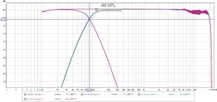
i try the 47k, no Leakage from L to R, but the amplitude decrees.
i go for 22k, Leakage about 10mv for 2v signal, i think its Negligible.
thanks
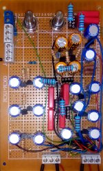
almost finish my B1 Active Crossover
Thanks everybody for the help
Finish my B1 crossover board:
2* 2th order HPF LR 86Hz filter for my OB speaker
Stereo to mono passive with 22k resistance
1*2th order LFP
The noise in the high freq is from the reference source, not from the board.
Thanks
Finish my B1 crossover board:
2* 2th order HPF LR 86Hz filter for my OB speaker
Stereo to mono passive with 22k resistance
1*2th order LFP
The noise in the high freq is from the reference source, not from the board.
Thanks
Attachments
it seems less interest for this great xo, but my OB will get the benefit of this treasure. Since no any pcb available, ptp is my only option. all layout only stored on my brain, i'm bad on using pcb software and paper drawing. just soldered all parts required, only need to finish the route which will be the hardest thing to complete.
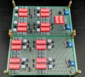
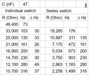
I'm using K170 pair with main feature from B4 with dip 8 switch to choose resistor value, jumpers for 6/12dB filter and also jumpers to bypass each pole. I put 4step of HF attenuator from 5-20dB with 5dB increment and this also can be bypassed.
Each pole can be configured from 75Hz until 320Hz when each individual switch is activated (basic need for OB), while it can go up yo 1.5kHz when the switch is activated in series (hopefully my calculation is correct)
still long way to finish
Attachments
I've been meaning to build a new active filter for a while, I decided to go the F4 style buffer instead of the DCB1.
It's a 24dB Sallen-Key with input buffer.
I haven't gotten round to prototyping this yet, so it may have bugs
If it's of any use to any one that wants to use it as a starting point for their own PCB, I'll post the KiCad files.
It's a 24dB Sallen-Key with input buffer.
I haven't gotten round to prototyping this yet, so it may have bugs
If it's of any use to any one that wants to use it as a starting point for their own PCB, I'll post the KiCad files.
Attachments
I've been meaning to build a new active filter for a while, I decided to go the F4 style buffer instead of the DCB1.
It's a 24dB Sallen-Key with input buffer.
I haven't gotten round to prototyping this yet, so it may have bugs
If it's of any use to any one that wants to use it as a starting point for their own PCB, I'll post the KiCad files.
Could you post the schematic please?
Rush
- Status
- This old topic is closed. If you want to reopen this topic, contact a moderator using the "Report Post" button.
- Home
- Amplifiers
- Pass Labs
- B1 Active Crossover