Hi Jeff,,
Yes I saw the note about adding the 22p caps to the underside. Thanks.
Is there a "latest" schematic for the OPS? Just looking it over and I see there are some differences from the Slewmaster. I assume there was goal in mind. Just wondering what that was and if I need to treat it differently.
Thanks again, Terry
Did you notice the components on the bottom side as well? There's a NTC hiding under there. This is very different than a Slewmaster. It looks like it has twin bias spreaders. I'm curious to see how it works. I've got all the pieces waiting, but haven't had time to build it.
Last edited:
Hi guys, sorry - gust woke up recently ")
The key difference of this OPS is a non-switching operation. The second spreader, together with the clamping diodes, sets the minimal bias voltage, preventing the output transistors from closing completely, resulting in crossover distortion minimization.
NJW3281/1302 can be used instead of Sanken output devices (with lower maximum output power), as well as MJE15032/15033 can be used for the drivers. No PCB changes required.
Just to clarify the overall situation for now - Vertical IPS is built and tested with IRFP-based Slewmaster OPS, the new now-switching OPS is not built and tested as yet.
Yes, schematic from the post #155 is "as built", with 2 caps under the board.
Cheers,
Valery
Did you notice the components on the bottom side as well? There's a NTC hiding under there. This is very different than a Slewmaster. It looks like it has twin bias spreaders. I'm curious to see how it works. I've got all the pieces waiting, but haven't had time to build it.
You guys are ahead of me on the OPS - I'm just ordering the boards now
Hi Valery,
What is the output current for the Vertical and what is the best way to set it? Can it be used with the standard Slewmaster ops?
With this non-switching ops, what should the bias be set to? I ordered Sankens for it. I will probably use the MJE15032/33 because I have those on hand.
Thanks, Terry
What is the output current for the Vertical and what is the best way to set it? Can it be used with the standard Slewmaster ops?
With this non-switching ops, what should the bias be set to? I ordered Sankens for it. I will probably use the MJE15032/33 because I have those on hand.
Thanks, Terry
Hi Valery,
What is the output current for the Vertical and what is the best way to set it? Can it be used with the standard Slewmaster ops?
With this non-switching ops, what should the bias be set to? I ordered Sankens for it. I will probably use the MJE15032/33 because I have those on hand.
Thanks, Terry
Hi Terry,
If I'm not mistaken, it's somewhat around 7mA now. I will let you know during the next few days. Anyway, it can be reduced further on by reducing R19, R20.
So, it should be possible to use it with the standard Slewmasters.
MJE15032/33 are perfectly fine.
Cheers,
Valery
AmpliWire - super-linear, rather fast VFA
Hello All,
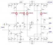
I continued thinking about the ways of making the VAS faster, more linear, keeping it stable at the same time. At some point, an idea came in - why don't I try to arrange the VAS stage in such a way, that it's somewhat "current-driven"? After trying some possible options - attached is what I came up with in the end - see attached.
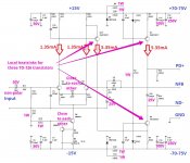
VAS output is arranged as two current sources, looking at each other. One of them is driven by the current from the single-ended VAS input transistor in a way, that its current is subtracted from the current, set by the bottom CCS's emitter resistor. The structure appears to be extremely linear and stable.
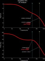
Note - there's no Miller compensation in place. Only RC in LTP and some light lead compensation. See AC analysis - very clean curves, single pole, 89 degrees / 19 db margins. Rather low loop gain.
I have simulated with GNFB loop open. 65 db overall gain, 0.06-0.08% THD throughout the audio range. With the loop closed - gain is 28.5 db, harmonics are below -100db. Clean clipping, symmetric slew, rather fast.
I have tried a number of fully symmetric configurations - driving both output CCSs - but no real benefits. This "pure" configuration is the best so far. Simple and efficient. Well, symmetric ones are good as well, but no justification of almost doubling the components count at the moment.
I suppose, this "current subtraction" approach is going to be useful in CFA front-ends as well. So far, I'm going to prototype and carefully test the one attached. BTW, this topology would be a great basis for a hybrid So many things to do!
If somebody wants to play with this thing - you're more that welcome
Cheers,
Valery
Hello All,
I continued thinking about the ways of making the VAS faster, more linear, keeping it stable at the same time. At some point, an idea came in - why don't I try to arrange the VAS stage in such a way, that it's somewhat "current-driven"? After trying some possible options - attached is what I came up with in the end - see attached.
VAS output is arranged as two current sources, looking at each other. One of them is driven by the current from the single-ended VAS input transistor in a way, that its current is subtracted from the current, set by the bottom CCS's emitter resistor. The structure appears to be extremely linear and stable.
Note - there's no Miller compensation in place. Only RC in LTP and some light lead compensation. See AC analysis - very clean curves, single pole, 89 degrees / 19 db margins. Rather low loop gain.
I have simulated with GNFB loop open. 65 db overall gain, 0.06-0.08% THD throughout the audio range. With the loop closed - gain is 28.5 db, harmonics are below -100db. Clean clipping, symmetric slew, rather fast.
I have tried a number of fully symmetric configurations - driving both output CCSs - but no real benefits. This "pure" configuration is the best so far. Simple and efficient. Well, symmetric ones are good as well, but no justification of almost doubling the components count at the moment.
I suppose, this "current subtraction" approach is going to be useful in CFA front-ends as well. So far, I'm going to prototype and carefully test the one attached. BTW, this topology would be a great basis for a hybrid
So many things to do! If somebody wants to play with this thing - you're more that welcome
Cheers,
Valery
Attachments
Hello All,
I continued thinking about the ways of making the VAS faster, more linear, keeping it stable at the same time. At some point, an idea came in - why don't I try to arrange the VAS stage in such a way, that it's somewhat "current-driven"? After trying some possible options - attached is what I came up with in the end - see attached.
VAS output is arranged as two current sources, looking at each other. One of them is driven by the current from the single-ended VAS input transistor in a way, that its current is subtracted from the current, set by the bottom CCS's emitter resistor. The structure appears to be extremely linear and stable.
Note - there's no Miller compensation in place. Only RC in LTP and some light lead compensation. See AC analysis - very clean curves, single pole, 89 degrees / 19 db margins. Rather low loop gain.
I have simulated with GNFB loop open. 65 db overall gain, 0.06-0.08% THD throughout the audio range. With the loop closed - gain is 28.5 db, harmonics are below -100db. Clean clipping, symmetric slew, rather fast.
I have tried a number of fully symmetric configurations - driving both output CCSs - but no real benefits. This "pure" configuration is the best so far. Simple and efficient. Well, symmetric ones are good as well, but no justification of almost doubling the components count at the moment.
I suppose, this "current subtraction" approach is going to be useful in CFA front-ends as well. So far, I'm going to prototype and carefully test the one attached. BTW, this topology would be a great basis for a hybrid
If somebody wants to play with this thing - you're more that welcome
Cheers,
Valery
I have to simulate it, looks as good idea.
Valery your picture are readable finally, not so big as before.
Damir
I can connect traces. Getting the parts in the right locations is what I struggle with.You're getting better at that. This looks like a good one for you to lay out.
You guys seem to do it with ease.
I'd be happy to play with it if you want to do a single layer layout.
Terry, I will make it single layer - simple enough
Hope it will fit 3' x 3' inch
I have to simulate it, looks as good idea.
Valery your picture are readable finally, not so big as before.
Damir
Damir, that would be great.
This is taken from my simulator - it shows schematics pretty well
Hi Valery,
As i am workshop forbiden yet for 4 weeks. I can try to layout this during weekend if you want : same form and board layout than other well known IPS (3"x3.937" =>76.2x100mm). Just if you could specify parts voltage rating...
Marc
Hi Marc,
That would be great. I have marked all the important things (hope so
). All unmarked resistors are normal 1/4W, all small caps are normal ceramics.250V sort of rating does not mean we expect 250V there - I just would like to have this kind of size / pin spacing for those caps
Please try to keep the input stage compact and make the "star" for the main ground - always good to have. This is going to be a cool one
Cheers,
Valery
Attachments
Are C1 and C20 bipolar electrolytics?
I usually use the normal polar ones - at couple of volts they see as a maximum, it does not really matter. Practical tests show they are ok - no difference.
- Home
- Amplifiers
- Solid State
- Revisiting some "old" ideas from 1970's - IPS, OPS