I also don't see any advantages of a more stable spindle speed or read rate. Better flatness or eccentricity will help to reduce the amount of work done by the servo systems, but will not improve the audio output.
I agree with your comment, except for that final part about about the audio output not being improved from reducing the work being done by the servo. While I think that can be made true for an well designed integrated disk player (transport with DAC), I do not think it so much true for seperate transport and DAC systems. Even though the S/PDIF data stream outputted by different transports should be bit identical, the clock jitter injected in to those streams is likely not to be. Among the many factors which can inject jitter is the amount of work performed by the servo.
Stable platter is useless for the simple reason that CD's do not have a constant RPM, the constant acc/deceleration on a heavy platter will not be beneficial, to the contrary.
Look at how the CD spinning. Look at the outer perimeter of the CD. May be because it is made of a flexible plastic, often we can see the CD surface moves up and down while spinning. Putting stabilization load on top is not possible because of weak motor. On the laser transport anyhow the CD spins so steadily.
Now the $ question is, will the CD vertical displacement during spinning affects sound quality of the last records in a CD in most cases?
When I've before considered building my own CD transport or player the many design implementation issues always put a quick stop to such thoughts. Issues such as, transport control software, user interface and control software (remote control, display data and control, etc.). Then there are the issues associated with constructing the enclosure, such as all of the precise front panel cut-outs for mounting the control buttons, and the display, and the disk access. While by no means impossible, I think it fair to describe this as daunting.
While new CD only transports have become scarce, there is no shortage of video optical disc transports, which will also play audio CDs. They are available new everywhere. Have all of the operational software written. Have enclosures that are professionally manufactured, and are available at all price points, including mass market. To see how the many readily available video disk players might be the best alternative for we DIY hobbyists, we need a basic definition of what constitutes a 'Quality CD mechanism'. There are only two fundamemtal technical requirements. First, that the data is transferred off the disk without error. Second, that the connected DAC can be supplied with a jitter-free clock that's synchronous with that data. Of course, there can be other requirements, such as dependability, mecahanical quietness, ease of use, etc.
I think that video disk players meet all of those above requirements save for one, that of supplying a jitter-free CD audio rate clock to the DAC. The fundamental solution to the jitter problem is, of course, to slave the transport's clock to a low-jitter, free running clock generated at the DAC. Asynchronous USB is a computer based implementation of this approach. Of course, there is an optical disk transport/player based DIY solution as well, which is to send the DAC's master clock signal to the transport via coaxial cable, while the audio data returns to the DAC via the existing S/PDIF link. However, there is often a problem with such S/PDIF based DAC as clock master with transport as clock slave arrangements, which is that the two master clocks may be of fundamentally different frequencies. While this is definitely true between video disc players and CD audio DACs, it can also be true between CD audio only transports and audio DACs. Simply sending an CD audio DAC's master clock signal to the transport to also serve as it's master clock signal is not possible with video disk players because of their differing frequency basis.
There is at least one workable solution to consider, which is what Guido Tent has proposed via his 'Tentlink' approach. The Tentlink synchronizes the transport clock and the DAC within a PLL loop that's physically split across the two chassis. The DAC's local XO serves as the PLL reference clock, while a VCXO in the transport serves as the clock being compared. In order to play 44.1kHz rate audio disks, video players synthesize the required CD audio sample rate clock signals from their non-CD related master clock frequencies. All that the split PLL then needs to do is lock the CD sample rate clock signals received from the transport via the S/PDIF link to the DAC's local master clock. It does this by 'pulling' the VCXO in the transport via a low bandwidth D.C. coupled two-wire link between the DAC and transport, just as it would if the PLL weren't physically split across two chassis. Voila' audio DAC as clock master with video transport as clock slave, with very low clock jitter at the DAC, utilizing a ready source (for now) of new optical disk transports/players available at mass market prices. Of course, this would require a small modification to the commercial video player, and so it is DIY only.
The short answer is No. Jitter is not a problem at this stage. Sound quality is not effected.
Ken, you would have to explain how this could have any influence.
Mark,
Jitter can be induced on to clock signals by a number of mechanisms. Among which are, oscillator phase noise - which itself has several causes, such as power supply noise, and the intrinsic properties of the oscillator. Also, logic induced modulation (LIM) - which essentially is supply rail and/or ground bounce noise induced by the pulsed impedance swinging of switching logic circuits, etc. High activity by the servo, much like LIM, could conceivably contaminate ground with noise noise currents that add to the jitter of a clock signal. It may only be a secondary effect, but the basic mechanism of supply induced noise adding to jitter is an established one. Any circuit that contributes to contaminating the supply or ground with noise can induce jitter.
Further adding to the potential for damage with an external DAC box is that switching induced noise can also produce common-mode noise across an unbalanced S/PDIF interface. That can induce yet additional jitter on the recovered clock signal at that end.
Because they are not produced any more. This was was mentioned over and over again in this thread. Check this for reliability:
Alright, I wasn't aware they already stopped production. That indeed means there's no reliable off-the-shelf CD-transport available one could use for a DIY CD-player. Or at least I've been unable to find one.
The Shigaclone seems interesting enough that it merits closer examination?
vicol audio : Shigaclone mkII CD transport
vicol audio : Shigaclone mkII CD transport
Ken, you are saying that the small servo currents in the player are going to upset a S/PDIF receiver and DAC. I would like to see some measurements on that.
That depends on your definition of small, and of upset. Are you saying that the servo assembly doesn't swing as much current as does an logic gate, which are well known to induce supply noise? If by upset, you mean add some amount of clock jitter, then yes. Clock jitter is essentially not an issue as far as provoking actual data errors across in these short consumer application data links.
What I will do is to help you to intellectually prove the reality of the mechanism for yourself. First, only a power supply with an absolutely zero impedance across a very wideband would not be susceptible to fast slewing load induced modulation. Even if you could create voltage regulators with such performance, the inductance on the printed circuit traces will exhibit some impedance, unless those perfect regulators are in shunt. As I had indicated, in a well engineered transport, the supply noise should be minimal. However, I doubt that all, or even a majority of transports be so well engineered. What you are left questioning then is the degree of the end effect.
I suggest that you download a CMOS logic family data-sheet, such as for the 74HC family. Find the graph showing gate prop. delay versus supply voltage. You will find that prop. delay can changed by nanosecond amounts by the supply voltage. Gate prop. delay modulation from supply noise directly produces jitter. Yes, these are relatively gross supply variation being graphed, but the jitter magnitude in question for audio on the order of picoseconds. Also, keep in mind that the prop. delay data is only for one gate. Think about the cumulative effect across a chain of many gates. I don't think it so far fetched to be concerned that a highly active servo may be adding some non-trivial amount of clock jitter. The fundamental mechanism is certainly present. The particular end degree of the effect will obviously be partly a function of the servo' supply design, and partly of the activity of the servo.
Last edited:
Hi Mark,
CD servos can most definitely upset other circuitry. The servos often run on unregulated supplies, or on their own supplies in very expensive CD players. Don't forget that the loads are motors and the focus & tracking coils in the laser head. Some CD players had a problem in that the heat generated could (and did) melt the plastic covers. Even with the KSS-210A head, which was well after this problem became known. The servo actuators are power amplifiers operating in class B (normally).
Hi Jay,
Look at the voltage across the disc motor and see how much activity there is going on there with many CDs. That motor is constantly correcting the speed of the disc. Then, you ask it to skip tracks and you'll really see an overworked motor.
-Chris
CD servos can most definitely upset other circuitry. The servos often run on unregulated supplies, or on their own supplies in very expensive CD players. Don't forget that the loads are motors and the focus & tracking coils in the laser head. Some CD players had a problem in that the heat generated could (and did) melt the plastic covers. Even with the KSS-210A head, which was well after this problem became known. The servo actuators are power amplifiers operating in class B (normally).
Hi Jay,
No. Put a flexible disc in a clamp and spin it. The edge will be level without undulations. Same thing as the path of a bit of string weighted. CDs are quite stiff actually, especially compared to the applied forces in a CD player. That fact is proved by the observation you made in that warps continue to exist while the CD spins.Look at how the CD spinning. Look at the outer perimeter of the CD. May be because it is made of a flexible plastic, often we can see the CD surface moves up and down while spinning. Putting stabilization load on top is not possible because of weak motor. On the laser transport anyhow the CD spins so steadily.
The added mass would also wear a more beefy motor compared to the spinning mass of only a CD. Also, the time constants built into the servos are tuned to the standard CD mass. Any additional rotating mass is going to adversely affect how well the motor can correct the speed. This does directly add jitter to the incoming data. Do not forget that before the data enters the memory, each bit is decided on its voltage level at specific points in time. Mess this up and you have lots of data errors that are loaded into memory where they will be clocked out nice and steadily as if there was no problem. Hmmmm, there's a problem here. Don't forget that the clock for incoming data is a PLL that may or may not remain locked for the entire cycle. It just does the best it can.Putting stabilization load on top is not possible because of weak motor.
No it doesn't!On the laser transport anyhow the CD spins so steadily.
Look at the voltage across the disc motor and see how much activity there is going on there with many CDs. That motor is constantly correcting the speed of the disc. Then, you ask it to skip tracks and you'll really see an overworked motor.
-Chris
Hi NATDBERG,
The thing that makes that mech. so good is the mixture of cast parts that have been milled accurately. They still need a polish to allow proper alignment, so if you do yours, finish off with 600 grit wet/dry sandpaper. You can go finer if you wish, but 600 would be the minimum. This mechanism allows you to orient the head in all dimensions, eliminating all angular errors. This is where most mechs. fall down. The result is a perfect eye pattern. Doing this taught me how to shim other mechanisms to improve a defect in alignment. My customers noticed this. They didn't know why, they did notice that discs that wouldn't play well before now did.
The one stupid problem with this transport is the genius that decided to run a belt on a motor shaft without using a pulley. Yours is probably slipping (feed belt). You can't just mount a pulley because that will throw off the feed motor gain. This is the one issue I would love to fix.
If a person is going to do work on an item, I expect them to actually know what they are doing and the principles behind how the item works. "I have never seen a problem" is hardly knowledge. There are people who work in the audio industry in technical capacities who do understand these things. If this was a good idea, it would be recommended to be done. Now wait for this. If doing this was at all positive, manufacturers would lead the charge - because it reduces their production costs and would be seen as a positive thing. Notice the lack of any such movement.
44.1 KHz output that requires a 7th order filter, except that no one uses this filter. The filter was not specified because it sounds great. It was designed to prevent damage to other equipment. If you do not over-sample the data, you are forced into using a sharp filter. If you don't use a filter, I can only assume that the reason is laziness, or ignorance. It's not as if you have to design this filter, just copy it from a schematic.
Because I have decades of training, and have been trained by those that came before me, I still have a duty to correct false ideas and prevent errors of ignorance. I am not using the word ignorant to say anyone is stupid. It simply means that a person has not done sufficient research and is genuinely unaware of the full truth. Some self control would be helpful in cases like that. The more you know, the more you know you don't know. There is a lot of truth to that.
-Chris
Well, at least I'm consistent.Over the years I've read your posts mentioning the OMS-7 (I have a broken one) and it's great mech. What makes it so good? The cast construction, laser, control circuitry?
The thing that makes that mech. so good is the mixture of cast parts that have been milled accurately. They still need a polish to allow proper alignment, so if you do yours, finish off with 600 grit wet/dry sandpaper. You can go finer if you wish, but 600 would be the minimum. This mechanism allows you to orient the head in all dimensions, eliminating all angular errors. This is where most mechs. fall down. The result is a perfect eye pattern. Doing this taught me how to shim other mechanisms to improve a defect in alignment. My customers noticed this. They didn't know why, they did notice that discs that wouldn't play well before now did.
The one stupid problem with this transport is the genius that decided to run a belt on a motor shaft without using a pulley. Yours is probably slipping (feed belt). You can't just mount a pulley because that will throw off the feed motor gain. This is the one issue I would love to fix.
Two reasons. The first is that it is technically wrong, as in incorrect. Decisions made by folks who don't understand the subject matter, are told a story and decide to throw in. The second is because some folks (internet modders) take money from people for this make work project. They prey on the lack of understanding and trade on people's trust. They give good technicians a bad name. No matter how these changes are made, I often have to clean up the mess. Sometimes the equipment is damaged beyond repair (hack artists are in good supply here). It is a pointless waste of money that the better technicians have to clean up after.As an aside, your frustration at NOS DAC builders is daft. Why is it of your concern what people do , why choose to be frustrated about it?
If a person is going to do work on an item, I expect them to actually know what they are doing and the principles behind how the item works. "I have never seen a problem" is hardly knowledge. There are people who work in the audio industry in technical capacities who do understand these things. If this was a good idea, it would be recommended to be done. Now wait for this. If doing this was at all positive, manufacturers would lead the charge - because it reduces their production costs and would be seen as a positive thing. Notice the lack of any such movement.
Not at all. The results of doing this can be shown easily with an oscilloscope. It is a known thing, not an imaginary problem.In some ways your approach is like telling explorers not to sail west too far because they will drop off the end of the earth or meet the big monster
Sorry, this is being recommended to other people without qualifying the procedure or results. Half a story presented as if it has been researched responsibly. It has not.Chill out, it is dac experimentation and even "dangerous" experimentation is beneficial even if you can say "I told you so" at the end (but who would be so callous as to do so?).
Exactly.Besides, NOS is about no digital filter and hence no oversampling
44.1 KHz output that requires a 7th order filter, except that no one uses this filter. The filter was not specified because it sounds great. It was designed to prevent damage to other equipment. If you do not over-sample the data, you are forced into using a sharp filter. If you don't use a filter, I can only assume that the reason is laziness, or ignorance. It's not as if you have to design this filter, just copy it from a schematic.
Actually, there is. However, someone who is not an expert wouldn't know about it. Survey the filters that were designed into audio products. Looky looky! They are all very similar. It sure sounds like there was a hard and fast rule. Ignorance again.there is no hard and fast rule about analogue filtering so you could well be barking up the wrong tree.
It does provide some loss at 44.1 KHz, but it is not a sharp filter. That's similar to saying that a gash didn't require 15 stitches, 2 will do nicely because there is no hard and fast rule. This is an extreme example, granted. But a little of a good thing that falls well short of what is required can't be lauded as a positive approach. Not for me anyway.A transformer coupled output for example provides filtering.
Because I have decades of training, and have been trained by those that came before me, I still have a duty to correct false ideas and prevent errors of ignorance. I am not using the word ignorant to say anyone is stupid. It simply means that a person has not done sufficient research and is genuinely unaware of the full truth. Some self control would be helpful in cases like that. The more you know, the more you know you don't know. There is a lot of truth to that.
-Chris
The Shigaclone seems interesting enough that it merits closer examination?
vicol audio : Shigaclone mkII CD transport
Just look at the clamper vicol audio uses.
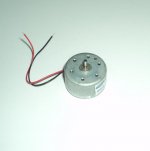
Would you like to use on this motor-2mm shaft, 1mm bearing, brushed design:
Attachments
The Shigaclone seems interesting enough that it merits closer examination?
vicol audio : Shigaclone mkII CD transport
...or on this one:
6mm shaft, 5mm bronce bearing + ruby bearing for carrying the weight and brushless design.
Attachments
I guess I do not need to explain that the Sanyo SFP-101N uses cheap Mabuchi Motors- like almost any of the current transports. And the Sanyo SFP-101N is not being produced either.
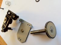
And now look at this, this is the goal: All magnetic, no gears, completetely serviceable:
And now look at this, this is the goal: All magnetic, no gears, completetely serviceable:
Attachments
Hi Salar,
I'm liking that one.
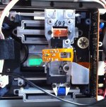
It looks like you have the photo mirrored from the display on the 'scope.
Now, can you figure out how to be able to adjust that head in three axis? It's possible. Adjust one rail support height for azimuth at the head support. The rest is more difficult and so I leave that for you. You could copy the OMS-7 setup. That ensures perfect alignment and also the fact that it stays aligned as it is locked in once the adjustments are done. It's like one solid hunk of metal at that point.
Hi rfbrw,
Nice to see you!
Ain't that the truth. You called it well.
-Chris
I'm liking that one.
It looks like you have the photo mirrored from the display on the 'scope.
Now, can you figure out how to be able to adjust that head in three axis? It's possible. Adjust one rail support height for azimuth at the head support. The rest is more difficult and so I leave that for you. You could copy the OMS-7 setup. That ensures perfect alignment and also the fact that it stays aligned as it is locked in once the adjustments are done. It's like one solid hunk of metal at that point.
Hi rfbrw,
Nice to see you!
.On the bright side, if one is going to disregard the rules of electronics then audio is probably the best place to do it.
Ain't that the truth. You called it well.
-Chris
The first time I read about that the servos may cause DAC/clock jitter, it was presented as an hypothesis that needed to be confirmed. 20 years later, it is presented as fact. Is there anyone who has measured or tested this?
If I started the rumour that its the ground noise produced by the power amps that really is the cause of jitter. How long would it take to become true?
The video I posted before shows the lens movement at the OD. See at 9:00.
https://www.youtube.com/watch?v=TFG2yNynq4A
Is that what is causing jitter on an external DAC?
Hi Jay,
No. Put a flexible disc in a clamp and spin it. The edge will be level without undulations.
I have observed the effect of the following:
(1) Not every plastic CD is pure flat.
(2) Some spindle motors have too long shaft.
(3) The CD clamp is not precise in putting the center of the CD in exact center of the motor shaft...
The added mass would also wear a more beefy motor compared to the spinning mass of only a CD.
Yes, I'm actually reluctant to try that approach because the added mass seems too much. But other approaches are even more difficult to realize.
Don't forget that the clock for incoming data is a PLL that may or may not remain locked for the entire cycle. It just does the best it can.
I like to turn on the error reporting of the PLL when applicable. How accurate do you think such error reporting?
No it doesn't!
Look at the voltage across the disc motor and see how much activity there is going on there with many CDs. That motor is constantly correcting the speed of the disc. Then, you ask it to skip tracks and you'll really see an overworked motor.
I was talking about disc steadiness in term of displacement where we cannot notice if the CD is spinning or not. In term of acceleration steadiness, dont forget that this is a transport for laser disc where the design load is heavier and has much greater momentum than a CD.
Mark,If I started the rumour that its the ground noise produced by the power amps that really is the cause of jitter.
How, exactly, do you know that power amp noise can't contribute? Where is your analysis that there is no mechanism for this? I can present an anlysis where inter-component ground-loop noise can add to clock jitter under the right circumstances. We are talking about picosecond level jitter. Actual meaurement would require access to a lab grade jitter analyzer, which I certainly don't have access to. I've set out an easy to understand basis for a mechanism where servo activity can add to clock jitter. The only question is the magnitude of such jitter, and whether that magnitude is audible. I fail to understand the basis of your intellectual incredulity about this.
Last edited:
- Home
- Source & Line
- Digital Source
- Quality CD-Mechanisms are long gone - let us build one ourselves!