Calculating F-3db for various filters
I will try, and before I rephrase the questions, let's see If I've understood your recommendations so far: Starting with the input filter shown on the schematic below I see it has a 4.7u capacitor in series and a 25K resistor parallel to ground. Entering those values into this calculator gives me a time constant of 117,500 microseconds (us) or an Fc of 1.35 Hz. Which seems fine for a woofer amp.
Let's say I raise the Fc value of that filter to 35 Hz for my mid-range amp, and use the same 25K resistor (simplicity's sake), Using one of the online filter calculators I get a value for the capacitor near .18u at the Signal Input for a time constant of 4500us or an Fc of 35.36 Hz. All is good so far - I hope. THEN let's look at some the other components for the mid-range driver amp...
From post # 683 -
Similarly, using the same ratio to reduce the dual, parallel 220uF PSU caps from the shematic below,I get approximately 18uF.
The ratio method seems to be a handy way to maintain a relationship between the Input, NFB and PSU caps, My questions before can be boiled down to this: Assuming I have correctly established capacitor values for the NFB and PSU on the Midrange amp - is there a way (or need) to calculate the Fc or time constant values for the NFB and PSU filters? (I don't know how to calculate since there is no simple fixed resistor to plug into an on-line calculator, though I noticed the use of the speaker impedance in this next quote - which is why I asked about how to factor the speaker's and the amp's input impedance earlier)
Of course the first question just leads me to more questions (less pressing, perhaps?), can the FB and NFB-shunt resistor values remain the same when tuning the capacitors for higher frequencies? or does changing the capacitors imply corresponding changes to these resistors? I am guessing the NFB-shunt variable resistor may need to be adjusted but perhaps only to address the lower voltage/lower gain desired for hi-fi in the Mid and Tweeter amp?
Sorry, the questions just seem to cascade upon one another... first and foremost, I'm looking to validate that I'm on the right track when optimizing components at amps dedicated to specific driver frequencies.
Thank you both so much for the dialogue.
Sixto.

Any chance you could split that into separate questions?
I found 7 off ?
I will try, and before I rephrase the questions, let's see If I've understood your recommendations so far: Starting with the input filter shown on the schematic below I see it has a 4.7u capacitor in series and a 25K resistor parallel to ground. Entering those values into this calculator gives me a time constant of 117,500 microseconds (us) or an Fc of 1.35 Hz. Which seems fine for a woofer amp.
Let's say I raise the Fc value of that filter to 35 Hz for my mid-range amp, and use the same 25K resistor (simplicity's sake), Using one of the online filter calculators I get a value for the capacitor near .18u at the Signal Input for a time constant of 4500us or an Fc of 35.36 Hz. All is good so far - I hope. THEN let's look at some the other components for the mid-range driver amp...
From post # 683 -
Also, for higher frequency-only amps:"...If you raise the high pass filter at the input you can also raise the RC value of the NFB and the PSU..."
If I follow this, then, my ratio for the mid-amp above is 35.36:1.35, which indicates I can reduce the dual (parallel) 470uF NFB caps in the diagram below to a single 35uF cap or dual 18uF caps."...If I change the input filter to 400Hz (for the 4kHz crossover) I can reduce the capacitors by a factor of 400:2, i.e the 20mF becomes 100uF for the PSU and the 120uF NFB cap becomes 600nF. This can be a plastic film type and could even be MKP..."
Similarly, using the same ratio to reduce the dual, parallel 220uF PSU caps from the shematic below,I get approximately 18uF.
The ratio method seems to be a handy way to maintain a relationship between the Input, NFB and PSU caps, My questions before can be boiled down to this: Assuming I have correctly established capacitor values for the NFB and PSU on the Midrange amp - is there a way (or need) to calculate the Fc or time constant values for the NFB and PSU filters? (I don't know how to calculate since there is no simple fixed resistor to plug into an on-line calculator, though I noticed the use of the speaker impedance in this next quote - which is why I asked about how to factor the speaker's and the amp's input impedance earlier)
For an 8ohms speaker I use 20mF as the PSU capacitance to give a 160ms RC, The NFB would use 120uF to give a 120ms RC to suit a 80ms RC input filter.
Of course the first question just leads me to more questions (less pressing, perhaps?), can the FB and NFB-shunt resistor values remain the same when tuning the capacitors for higher frequencies? or does changing the capacitors imply corresponding changes to these resistors? I am guessing the NFB-shunt variable resistor may need to be adjusted but perhaps only to address the lower voltage/lower gain desired for hi-fi in the Mid and Tweeter amp?
Sorry, the questions just seem to cascade upon one another... first and foremost, I'm looking to validate that I'm on the right track when optimizing components at amps dedicated to specific driver frequencies.
Thank you both so much for the dialogue.
Sixto.
Last edited:
Don't change the local decoupling capacitors. These only work @ Medium and high frequencies, so you can't scale them back like we have described for the low frequencies that get applied to the PSU smoothing capacitors.I will try, and before I rephrase the questions, let's see If I've understood your recommendations so far: Starting with the input filter shown on the schematic below I see it has a 4.7u capacitor in series and a 25K resistor parallel to ground. Entering those values into this calculator gives me a time constant of 117,500 microseconds (us) or an Fc of 1.35 Hz. Which seems fine for a woofer amp.
Let's say I raise the Fc value of that filter to 35 Hz for my mid-range amp, and use the same 25K resistor (simplicity's sake), Using one of the online filter calculators I get a value for the capacitor near .18u at the Signal Input for a time constant of 4500us or an Fc of 35.36 Hz. All is good so far - I hope. THEN let's look at some the other components for the mid-range driver amp...
From post # 683 - Also, for higher frequency-only amps: If I follow this, then, my ratio for the mid-amp above is 35.36:1.35, which indicates I can reduce the dual (parallel) 470uF NFB caps in the diagram below to a single 35uF cap or dual 18uF caps.
Similarly, using the same ratio to reduce the dual, parallel 220uF PSU caps from the shematic below,I get approximately 18uF.
The input filters set the amplifier passband. You used the RC values for the low pass filter and used the CR values for the high pass filter.The ratio method seems to be a handy way to maintain a relationship between the Input, NFB and PSU caps, My questions before can be boiled down to this: Assuming I have correctly established capacitor values for the NFB and PSU on the Mid range amp - is there a way (or need) to calculate the Fc or time constant values for the NFB and PSU filters?
The amplifier has to properly handle this range of frequencies. The NFB must be arranged to properly amplify the whole passband, This can be done by using the DC blocking capacitor as a "filter"/gain adjust that passes the input signal and gradually roll-off the extreme low bass. The NFB high pass effect is also an RC (1kVR and 470uF*two) F-3dB ~1/2Pi1kohms940uF This frequency has to be LOWER than the input filter. It was suggested a long time ago that the minimum gap between these be half an octave (sqrt(2) lower) and the NFB works well at handling the signal that passes the input filter. (I carried out extensive listening tests and found I agreed). Similarly the PSU must be able to handle (supply changing current) that the NFB is asking for. Here again there is a filter effect. The PSU smoothing capacitance is the C and the speaker is the R. But only one half of the dual polarity PSU works in supplying current at a time. If you have 10mF and an 8ohms speaker the CR defines the frequency.
you don't need an online calculator. Just use fr =1/2PiRC(I don't know how to calculate since there is no simple fixed resistor to plug into an on-line calculator,
Looks like all your other comment has correctly followed what I was suggesting.though I noticed the use of the speaker impedance in this next quote - which is why I asked about how to factor the speaker's and the amp's input impedance earlier)
Of course the first question just leads me to more questions (less pressing, perhaps?), can the FB and NFB-shunt resistor values remain the same when tuning the capacitors for higher frequencies? or does changing the capacitors imply corresponding changes to these resistors? I am guessing the NFB-shunt variable resistor may need to be adjusted but perhaps only to address the lower voltage/lower gain desired for hi-fi in the Mid and Tweeter amp?
Sorry, the questions just seem to cascade upon one another... first and foremost, I'm looking to validate that I'm on the right track when optimizing components at amps dedicated to specific driver frequencies.
Thank you both so much for the dialogue.
Sixto.
Last edited:
Summarising all the above.
Set the passband with the low pass and high pass input filters.
Set the NFB at least half an octave below the high pass input filter.
Set the PSU at least half an octave below the high pass NFB.
eg.
for a mid range driver with a crossover that limits the audio to 300Hz to 3000Hz you can use a bandlimited amplifier that has a passband of 30Hz to 30kHz.
The NFB should be lower than 30/sqrt(2) <=21.2Hz
Your selected NFB components come to 19Hz.
The PSU should be lower than 19/sqrt(2) <=13.4Hz
For 8ohms Mid range this would be >=1.48mF use either ±1.5mF, or ±2.2mF
Summarising all the above.
Set the passband with the low pass and high pass input filters.
Set the NFB at least half an octave below the high pass input filter.
Set the PSU at least half an octave below the high pass NFB.
eg.
for a mid range driver with a crossover that limits the audio to 300Hz to 3000Hz you can use a bandlimited amplifier that has a passband of 30Hz to 30kHz.
The NFB should be lower than 30/sqrt(2) <=21.2Hz
Your selected NFB components come to 19Hz.
The PSU should be lower than 19/sqrt(2) <=13.4Hz
For 8ohms Mid range this would be >=1.48mF use either ±1.5mF, or ±2.2mF
I'm almost there...I got the process of tuning the Input filter pass-band and the NFB filter. I need to backtrack a bit on the PSU filter, though - I believe I was mistakenly thinking that when we referred to the PSU filter, we were talking about the filtering function of the pair of dual 220uF power caps on the amp board schematic. I now realize those are the de-coupling caps, and I should have been looking at the capacitor bank on the separate PSU board. If this is correct, then the question of tuning the PSU to the 3 amps gets more complex.
My confusion was compounded by a number of other posts and schematics on this thread showing a range of decoupling capacitors, generally tending to use bigger capacitance values in order to improve the low-frequency performance of the amps. I'm all in favor of using the same de-coupling scheme for all 3 amps if that is not where the tuning should be taking place.
Now, on to the PSU board itself: I've been planning to use one PSU to feed all 3 amp-boards plus the active crossover board within each speaker enclosure (250va toroid with dual rectifiers and one shared bank of capacitors.) All the drivers in each speaker enclosure are 8 ohms, so the same PSU calculation above still holds. This approach means the ratio between the PSU capacitors and the NFB/Signal-input filters on each of the Bass, Mid or Treble amps will be different. Assuming the PSU capacitor bank is sized to handle the combined load... am I missing an opportunity here, or is this an acceptable approach?
One alternative I have seen is a PSU configuration for a 3-way speaker that fed 3 separate banks of capacitors from a single toroid transformer and dual rectifiers. Is that a better way to tune the system, rather than sharing one bank of capacitors among all 3 amps? I may have to try for myself and see if I can hear the difference.
I will draw a schematic of the whole system I'm planning and post it soon to have a common reference for future discussion...
Thanks! - Sixto
If you had three wideband speakers being fed from three wideband amplifiers I would find it easy to answer your question.
The total load seen by the PSU is an effective 2.7ohms (8ohms/3)
This determines the total capacitance in the PSU.
But you are planning one LF amp, one MF amp and one HF amp with their loads.
In this situation the PSU does not see 2.7ohms, possibly nearly as high as 8ohms.
Maybe design for 6ohms, to allow for some current demand by the MF amp/speaker.
Without a loss (some form of resistance) there can be no filter. So, on most boards, a power filter does not exist.I'm almost there...I got the process of tuning the Input filter pass-band and the NFB filter. I need to backtrack a bit on the PSU filter, though - I believe I was mistakenly thinking that when we referred to the PSU filter, we were talking about the filtering function of the pair of dual 220uF power caps on the amp board schematic.
A fix for that is not especially difficult.
Understood, but...
Agreed, not difficult, but what is the reason to add resistance to the Decoupling caps locally as opposed to calculating the filtering value of the total PSU capacitance and driver impedance?
Three things made me wonder about that: one was AndrewT's reference to the driver's impedance as a resistance (which is a fact, but seems somewhat removed from the PSU, so that got me thinking about the whole amp-board having a form of resistance that would work in combination with the filter and de-coupling caps.
The second thing was that caps by themselves are often used as tweeter protection filters, again I assume that they are working in combination with the driver's impedance.
Finally, from some earlier comments on this thread I noticed reference to some decoupling cap size as being too small (not sure what too-small meant in this context) http://www.diyaudio.com/forums/chip-amps/226437-optimizing-tda7294-output-33.html#post3373045 But it made me think the de-coupling caps (which are kind of part of the PSU) may be performing some sort of filtering (even without a resistor nearby). I also find it interesting that the TDA7293 datasheet calls for even larger decoupling (1000 uF).
I understand that the primary function of the decoupling caps is to minimize inductance noise from the remote PSU boards, so I agree with the recommendations to keep the wires between PSU and Amp Boards short, or in some cases, build the PSU cap array right on-to the amp board (not practical in my case with 3 amps to feed) but I'm also thinking the de-coupling caps ought to be included into the PSU filtering/sizing calculations.
So is it just the driver impedance that works to resist the PSU current, or does the whole amp/driver impedance need to be factored in concert with the PSU capacitance to filter out undesirable frequencies? The driver seems simple enough to measure or estimate as AndrewT mentioned. The whole amp/driver impedance concept is a mystery to me.
I am now in the process of reading up on PSU capacitance and filtering action of various cap-bank sizes on some other threads... lots of suggestions, some of them conflicting. Will see if I can make sense of it all. Off to a long weekend in the north woods of Minnesota.
Sixto
Without a loss (some form of resistance) there can be no filter. So, on most boards, a power filter does not exist.
A fix for that is not especially difficult.
Agreed, not difficult, but what is the reason to add resistance to the Decoupling caps locally as opposed to calculating the filtering value of the total PSU capacitance and driver impedance?
Three things made me wonder about that: one was AndrewT's reference to the driver's impedance as a resistance (which is a fact, but seems somewhat removed from the PSU, so that got me thinking about the whole amp-board having a form of resistance that would work in combination with the filter and de-coupling caps.
The second thing was that caps by themselves are often used as tweeter protection filters, again I assume that they are working in combination with the driver's impedance.
Finally, from some earlier comments on this thread I noticed reference to some decoupling cap size as being too small (not sure what too-small meant in this context) http://www.diyaudio.com/forums/chip-amps/226437-optimizing-tda7294-output-33.html#post3373045 But it made me think the de-coupling caps (which are kind of part of the PSU) may be performing some sort of filtering (even without a resistor nearby). I also find it interesting that the TDA7293 datasheet calls for even larger decoupling (1000 uF).
I understand that the primary function of the decoupling caps is to minimize inductance noise from the remote PSU boards, so I agree with the recommendations to keep the wires between PSU and Amp Boards short, or in some cases, build the PSU cap array right on-to the amp board (not practical in my case with 3 amps to feed) but I'm also thinking the de-coupling caps ought to be included into the PSU filtering/sizing calculations.
So is it just the driver impedance that works to resist the PSU current, or does the whole amp/driver impedance need to be factored in concert with the PSU capacitance to filter out undesirable frequencies? The driver seems simple enough to measure or estimate as AndrewT mentioned. The whole amp/driver impedance concept is a mystery to me.
I am now in the process of reading up on PSU capacitance and filtering action of various cap-bank sizes on some other threads... lots of suggestions, some of them conflicting. Will see if I can make sense of it all. Off to a long weekend in the north woods of Minnesota.
Sixto
The PSU is a filter.Without a loss (some form of resistance) there can be no filter. So, on most boards, a power filter does not exist.
A fix for that is not especially difficult.
Most Builders refer to just the C and omit the full PSU .
I have adopted (some years ago) rC, where r is the impedance in the PSU circuit that creates the RC filter.
When others refer to CRC, I use rCRC because there are two cascaded filters, not one.
The first r is important. That is what creates the filter. A C alone cannot filter.
At it's simplest, r= sum of the resistances in the secondary winding + the resistance of the secondary to rectifier connections + the resistances of the rectifier connection + the resistance of the rectifier to smoothing capacitor wiring + the resistance of the capacitor connections + the return route resistances back to the Source/secondary winding.
That sum of all those resistances is not zero. It could be 0r1, or 10r, or anywhere in between, depending on what power capability you are assembling for.
In addition to the pure resistance r, there is also some inductance. LC is also a filter.
Maybe I should more correctly use (r+l)C instead of rC, where r alone implies that there is no inductance.
For the time being I will continue to use rC until more of the Membership starts to recognise the presence of the filter in the PSU.
Last edited:
Cost is a fair reason.Agreed, not difficult, but what is the reason to add resistance to the Decoupling caps locally as opposed to calculating the filtering value of the total PSU capacitance and driver impedance?
Before I get chatty, I'd like to say that the diode datasheets with helpful charts are ever so much easier than utilizing a really customized dc umbilical cable for it. It is really difficult to talk about so much BS/snakeoil and make sense of it; however, datasheet graphs are so much easier. And then there's this:
With a power amplifier, the second lowest cost location of a CRC's "R" is at the edge of the amplifier board.
The very lowest cost, theoretically, would be at small signal; however, quad rails also causes an expense, which could be more costly if one had to resort to regulators.
Compare:
If one had positioned the CRC's "R" (loss) anywhere in-between the transformer and the power supply reservoir capacitance, that immediately and directly costs a high amperage transformer to defeat that error. If I hadn't managed anything else, at least I have manged to defeat that particular cost increase--You won't be needing to do that to a power amplifier.
That above bit was strictly unimportant, practically.
Actually the real reason to do it involves simultaneous leverage in stability and imaging/3d/realism...which are items normally in conflict; so, I think it absolutely fantastic for any item to have assisted in both concerns simultaneously, at such low cost. In my case it was 3db multipled by 36 times.
3db multiplied by 36 times is like 108db, according to my calculator. There's a goodly chance that calculator hasn't worked very well, due to operator error. And whether it did or didn't, that wouldn't be important. What is important is that you're going to notice. And, what is really important is if you liked it.
Due to the fact that a quad rails approach and/or a composite/nested approach (all of that is exactly the same thing) will surely work better, I propose that my approach is propositioned as an easier, lower cost alternative.
Can a composite do better than my 108db noise reduction? Yes! And is it easier? Nope!
If I hadn't managed to say anything else then there's this: Before you consider amplifying, please do consider noise reduction, so that you don't amplify noise.
Therefore, I've proposed a really, low cost, filter to cut noise. Well, I like it!
Last edited:
That is excellent. I wish it weren't expensive.The PSU is a filter.
Most Builders refer to just the C and omit the full PSU .
I have adopted (some years ago) rC, where r is the impedance in the PSU circuit that creates the RC filter.
When others refer to CRC, I use rCRC because there are two cascaded filters, not one.
The first r is important. That is what creates the filter. A C alone cannot filter.
At it's simplest, r= sum of the resistances in the secondary winding + the resistance of the secondary to rectifier connections + the resistances of the rectifier connection + the resistance of the rectifier to smoothing capacitor wiring + the resistance of the capacitor connections + the return route resistances back to the Source/secondary winding.
That sum of all those resistances is not zero. It could be 0r1, or 10r, or anywhere in between, depending on what power capability you are assembling for.
In addition to the pure resistance r, there is also some inductance. LC is also a filter.
Maybe I should more correctly use (r+l)C instead of rC, where r alone implies that there is no inductance.
For the time being I will continue to use rC until more of the Membership starts to recognise the presence of the filter in the PSU.
I've been looking for ways to cut the costs. There's not many.
The r of rC costs nothing !I wish it weren't expensive.
That is what creates the filter.
A C alone is not a filter.
The very first R is the transformer. That part is spendy.The r of rC costs nothing ! That is what creates the filter. A C alone is not a filter.
Cost is a fair reason...Actually the real reason to do it involves simultaneous leverage in stability and imaging/3d/realism...which are items normally in conflict; so, I think it absolutely fantastic for any item to have assisted in both concerns simultaneously, at such low cost. In my case it was 3db multipled by 36 times...
Daniel, I must have missed this reply while I was working on sketches. Sounds good to me too. - I will revise the amp-board diagram to add a resistor between the power diodes and first de-coupling cap on both the +VDC and -VDC. One question about sizing the resistor for this Low-Pass filter, what criteria should I use for the F-3db value at this location? Amps generally like dead-flat, noise-free DC power, so is there any reason not to make this filter as low as possible, say 0.1 Hz or even less?
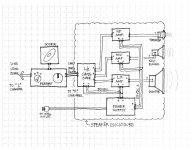
Here is a first-sketch of the active speaker's main components... By the way... how do I make this a thumbnail that gets enlarged when viewers click on it?

Thanks - Sixto.
Here's the thumbnail below, (saves space, right? but I can't read it.) I can attach it, but just haven't figured out how to let viewers enlarge it (and see more detail) by clicking on it.

DIYaudio's manage attachments automatically sets the first post display to show Thumbnail/s
One then has the choice of whether to click on the Thumbnail to expand to fill the screen if too big, or expand to full size if smaller than the screen.
Or if coming back to the page/post, one does not need to expand and reads around the Thumbnail.
One then has the choice of whether to click on the Thumbnail to expand to fill the screen if too big, or expand to full size if smaller than the screen.
Or if coming back to the page/post, one does not need to expand and reads around the Thumbnail.
Yes, that follows the standard DIYaudio attachment.
I see the Thumbnail (150x116 pixels).
I click on the Thumbnail and it expands until either the height, or the width, fills my firefox window (1126x870 pixels). I click on the X and it expands to full size (2200x1700 pixels).
Too big for my 1920x1080 monitor: you could crop and/or size your file so that you and we can see details. Bigger is not any advantage. When you are happy with the final "all details" pixel size, save and then attach the optimised file.
Last edited:
For sure, those were chosen with great care. They work down to bari harmonics (just far enough to promote hear-able bass). It is possible scale them back to a parallel pair of 100uF (or possibly smaller) if the task happened to be driving only a tweeter with a rather lovely flat response (and even more likely to work if that was a somewhat dull tweeter). Crudely stated: If the size goes down, the shout goes up and so does the treble resolution. That's really a hack. So long as the particular treble driver involved, and application, has allowed us to get away with it, then I have no idea why we shouldn't do it.Don't change the local decoupling capacitors. These only work @ Medium and high frequencies, so you can't scale them back like we have described for the low frequencies that get applied to the PSU smoothing capacitors.
*This post doesn't apply to full bandwidth amplifiers.
My apologies! I'm just not smart enough to figure resistor values suited for placement in series to high amperage rails of power amplifiers. Therefore, I use diodes for that task (as indicated in my schematics), not only because they happen to work delightfully, but also that their really convenient datasheets tell me what will happen, without the requirement of any guesswork on my part. Therefore, it is my opinion that notion of series resistors on the rails, should be reserved for preamplifiers and other low current needs--definitely not power amplifiers.One question about sizing the resistor. . .
- Status
- This old topic is closed. If you want to reopen this topic, contact a moderator using the "Report Post" button.
- Home
- Amplifiers
- Chip Amps
- Optimizing TDA7294 Output