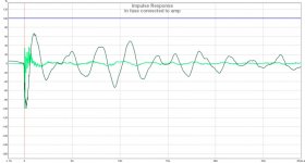
Plot the Impulse Response (tab above) and that will show polarity. A positive going peak means correct polarity (+ve pushes cone outwards). I did not expect reverse polarity to have such a different (worse) frequency response. Odd.
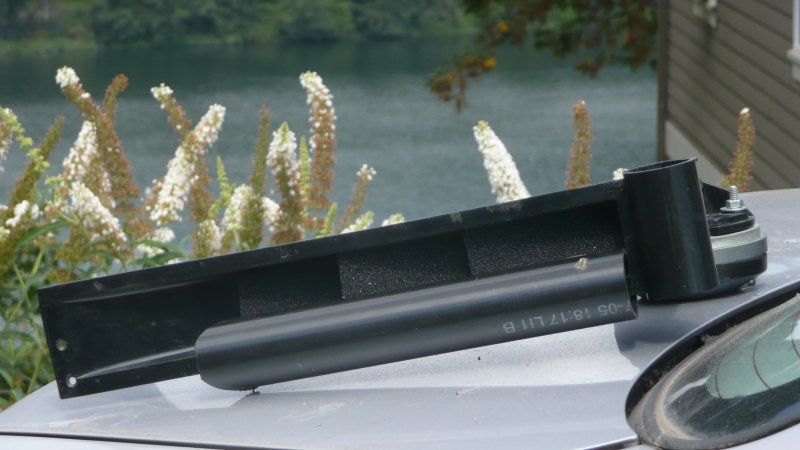
Throat photo looks very nice. Great craftsmanship in wood there.
Kees, if you don't mind inserting your posted images into the main body and providing captions. Otherwise we don't know what we are looking at.
To do this, right click on thumnail image and select copy image link url. The click the insert image icon in the post editor and paste the picture link. It will insert into the body something like this:
" url of your image here [\IMG]"
For example:
Reversed polarity from above image 1:
[IMG]https://www.diyaudio.com/forums/attachments/full-range/507587d1444142121-presenting-trynergy-full-range-tractrix-synergy-synergy-plot1.jpg
Last edited:
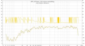
Did as a test measure the headphone who is most of the case lineair and see also dips and I think the wifi transmittor on the roof still do give radiation problems, the antenne give 6 a 8 watts of rf power because it has a reach of 15 km.
Or the problem is the pc input so I make a amp first so I can remove the long cheap thin signal wire.
If you compare that, and see it good, I have some over compensation of the horn, so it is so important to have a good measurement
system.
regards
Or the problem is the pc input so I make a amp first so I can remove the long cheap thin signal wire.
If you compare that, and see it good, I have some over compensation of the horn, so it is so important to have a good measurement
system.
regards
Attachments
Plot the Impulse Response (tab above) and that will show polarity. A positive going peak means correct polarity (+ve pushes cone outwards). I did not expect reverse polarity to have such a different (worse) frequency response. Odd.
Throat photo looks very nice. Great craftsmanship in wood there.
Kees, if you don't mind inserting your posted images into the main body and providing captions. Otherwise we don't know what we are looking at.
To do this, right click on thumnail image and select copy image link url. The click the insert image icon in the post editor and paste the picture link. It will insert into the body something like this:
" url of your image here [\IMG]"
For example:
Reversed polarity from above image 1:
[IMG]https://www.diyaudio.com/forums/attachments/full-range/507587d1444142121-presenting-trynergy-full-range-tractrix-synergy-synergy-plot1.jpg
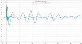
I expect the measuring distance is responsible for the huge change in the FR plot, the second picture with reversed wiring seems more in line with the other graphs. It looks like measurements further from the mouth there are more disruptions to the phase (not real phase turns but reflection/diffraction from the mouth?).
Here's the second one, only showing turns in higher frequencies:
Easier to read the phase plot this way and starting at zero degrees.
A plot of the impulse would help trace down the problems. Maybe a measurement with an absorber or round foam extension around the mouth?
And damp the horn with cld...
I'd use round pipe insulation on both flat horn lips to see what it does. Easy to test!
Something like this, but a bit more careful applied:
But Kees is right to want to get a proper mic amp running. I started with measurements with amplification from the sound card, bad idea.
Last edited:
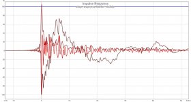
Did a measurement with two meters distance, just to see what happens, I did include the impulse also.
for comparing I did one with the open baffle, also a lot of dips, so room? or the mike, I go build the
from linkwitz, these do very wel.
regards
for comparing I did one with the open baffle, also a lot of dips, so room? or the mike, I go build the
from linkwitz, these do very wel.
regards
Attachments
Last edited:
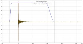
Now zoom in on the first ~20 ms of that impulse...
On that same impulse tab page you can also put a check mark (vinkje) to show the STEP.
Yes I now I do not yet be used on REW, I did start loudspeakers not as long ago. Maybe I have to try more speakers
in it, also without soft surround.
bedankt voor de tip.
Attachments
Last edited:
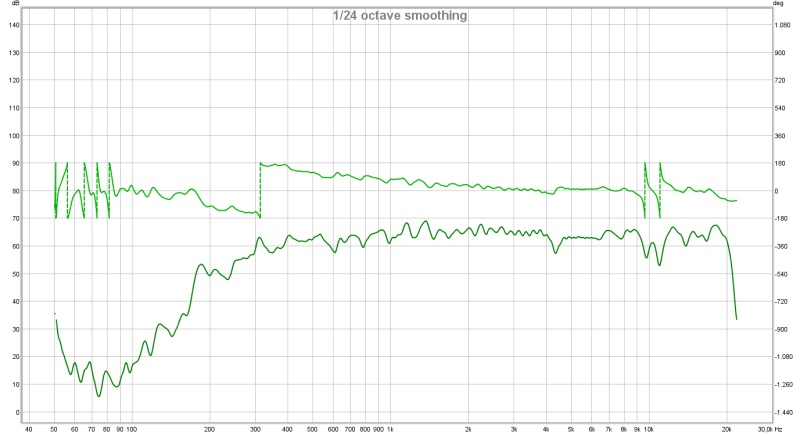
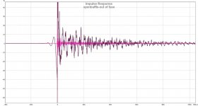
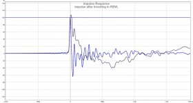
This plot shows the initial spike going negative (also the step starts negative) so you have reverse polarity here.
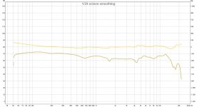
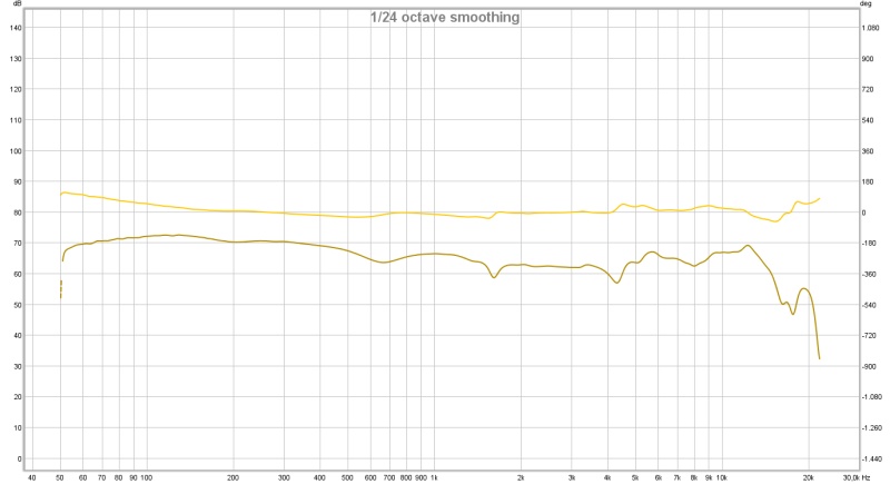
You may want to select default 1/12th octave smoothing - easier on the eyes and provides enough detail. Also, make measurement at 0.5m with horn mouth at least 36in off of the floor, then select 4ms to 5ms gate to get rid of reflections from floor and walls. Plot data from 300Hz and up.
These are all REW basics that you will get the hang of quickly. It is very easy to use and powerful software.
As expected, the biggest peak is down. So it's hooked up in negative polarity. It looks like you have Envelope ticked as well, I see double with both that and the step and impulse .
Envelope isn't needed here (vinkje uit). We do see some restlessness in the first millisecond.
.Envelope isn't needed here (vinkje uit). We do see some restlessness in the first millisecond.
This plot shows the initial spike going negative (also the step starts negative) so you have reverse polarity here.
You may want to select default 1/12th octave smoothing - easier on the eyes and provides enough detail. Also, make measurement at 0.5m with horn mouth at least 36in off of the floor, then select 4ms to 5ms gate to get rid of reflections from floor and walls. Plot data from 300Hz and up.
These are all REW basics that you will get the hang of quickly. It is very easy to use and powerful software.
I have checked the polarity but is shure connected the right way to the amp, output to + speaker and so on, only horn is connected.
So what happens here.
I have double check the amplifier connections, all are right, something else do shift fase?, possible the pc mic input or the mic who is not altered, and so there happens a fase shift on the Jfet in that mike, but will this do make impact I do not now, so I do first make the amp so I can use line input.
I go use Plasticine for the fase plug making one as a test with this Plasticine I can make easely a model, is good idea.
regards
I go use Plasticine for the fase plug making one as a test with this Plasticine I can make easely a model, is good idea.
regards
Attachments
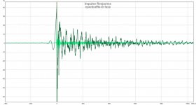
Yet your headphone measurement is in phase:
I'd check with a 1.5 volt battery and watch the cone movement of the Visaton to be sure. Whichever wire is touching the positive terminal on the battery carries the positive signal. If that signal pushes the speaker up, then your polarity is correct, if not, switch.
I'd check with a 1.5 volt battery and watch the cone movement of the Visaton to be sure. Whichever wire is touching the positive terminal on the battery carries the positive signal. If that signal pushes the speaker up, then your polarity is correct, if not, switch.
Last edited:
Yet your headphone measurement is in phase:
I'd check with a 1.5 volt battery and watch the cone movement of the Visaton to be sure.
I have did check with a battery, and the headphone was connected to headphone output of the pc, not the amp itselfs, do now is the hybrid amp the problem, out of phase output!!.
Or the horn shifts fase somehow.
I go try the other output of that amplifier, who is a self designed hybrid.
regards
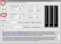
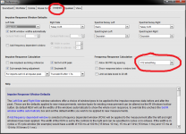
kees52 if setup for amp or microphone chain reverse polarity some where then there's a general setting into REW that can correct.
At top right corner hit the wrench icon and see picture one below for location, also when you are there see picture two how to get REW present plots as default 1/12 smoothing as xrk971 requested.
At top right corner hit the wrench icon and see picture one below for location, also when you are there see picture two how to get REW present plots as default 1/12 smoothing as xrk971 requested.
Attachments
Last edited:
kees52 if setup for amp or microphone chain reverse polarity some where then there's a general setting into REW that can correct.
At top right corner hit the wrench icon and see picture one below for location, also when you are there see picture two how to get REW present plots as default 1/12 smoothing as xrk971 requested.
Thanks
the 1/12 smoothing I have already found and corrected, the rest I go also, thanks for learning me.
I have now the mic amp, with a low noise opa 2134 and a diy mic capsule, tomorrow I get some clips and batteries so I can do it the right way.
also get horn higher, because I did measure from a table 30 cm above ground, but table do reflect also, and so I learn more then only woodworking and amps.
regards
I've been following the thread actually, very interesting concept. I'm not sure how to make the WAF high enough to use it in my home though... But if I'm buying a larger house I'll make a home cinema with some kind of Synergy speakersMy re-post over on your 3d thread worked
Hoping you can help Kees out with a phase plug Onni. 2in x 2in square throat - what can we do? I am sure you have some good ideas...
Thanks,
X
Is the speaker cone larger than the entrance and connected with this?
That could already be considered a phase plug and is probably partly why the response already is very good. I don't have any suggestions straight off. Might be good to focus on the rest of the task and later return to this when all else (injection ports and crossover) is working
/Anton
I've been following the thread actually, very interesting concept. I'm not sure how to make the WAF high enough to use it in my home though... But if I'm buying a larger house I'll make a home cinema with some kind of Synergy speakers
Is the speaker cone larger than the entrance and connected with this?
That could already be considered a phase plug and is probably partly why the response already is very good. I don't have any suggestions straight off. Might be good to focus on the rest of the task and later return to this when all else (injection ports and crossover) is working
/Anton
Hi Anton
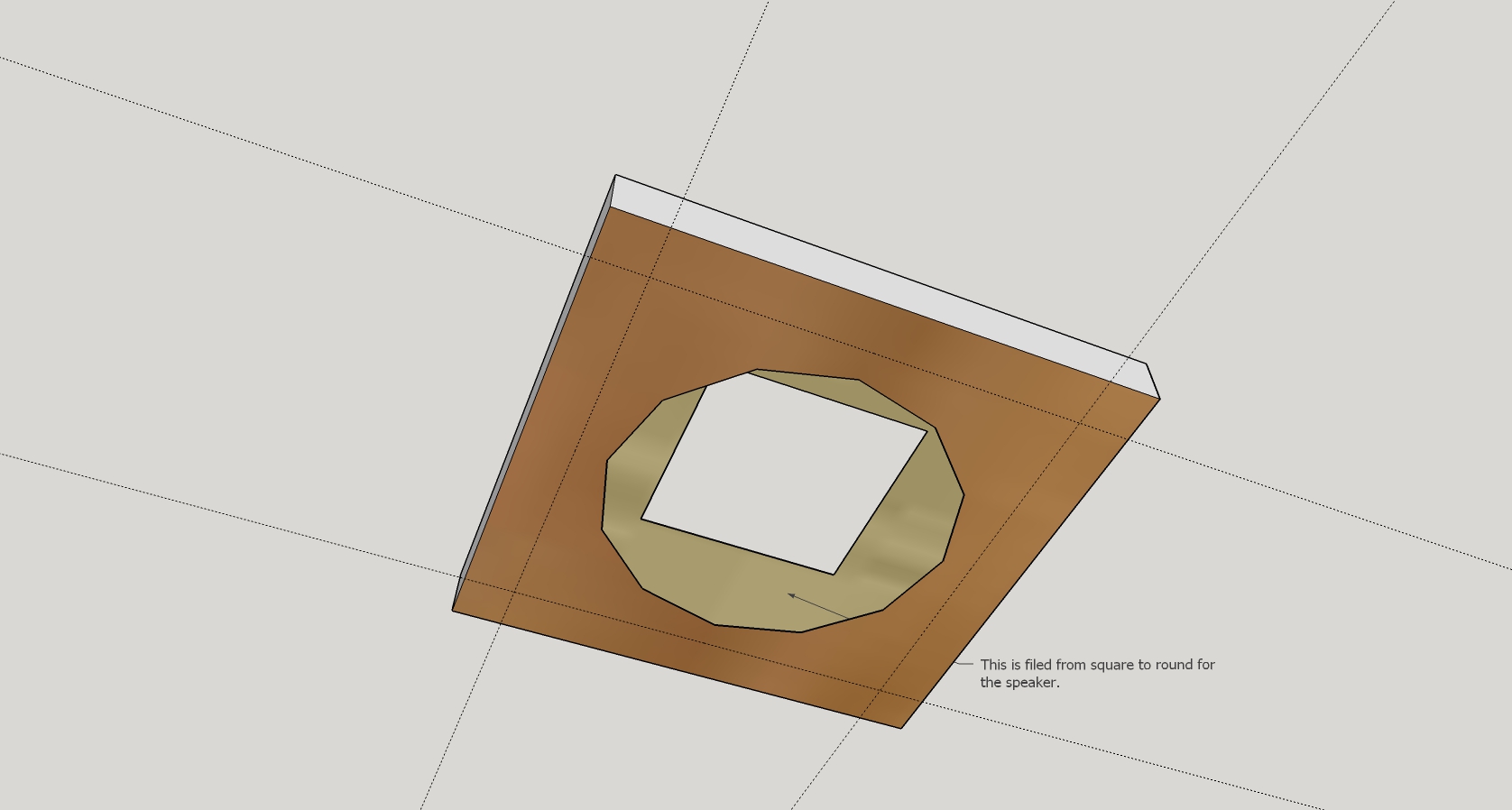
The room between cone and the throat is larger I file it from round to square part, Idea is to make it smaller when a fase plug fits in, but see different conceps on the internet, but miss the earea where air has to pass through without problems, the square is 4.5 by 4.5 cm, and speaker 6.8 cm total inc rubber surround on cone, only cone is 5.5 cm, so minus max excursion slot has to be 5.2 cm . I go get some Plasticine who get hard without a oven to test some things.
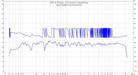
But I have inverted the input on REW and put Horn higher and more in a corner, but still not high enough like one meter and get this respons, but I finsh tomorrow the good mic amp and mike to get even better results.
But picture looks good, even more high output as you see when correcting the sound card cable who is quite long.
I have now put text on the measurements what and how I did it for clearity.
PS I have not trouble with WAF, I have none, I only dream sometimes
.regards
Attachments
Last edited:
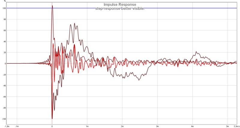
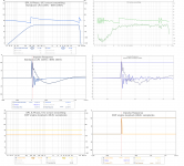
kees52 your data looks good.....
Below is live DSP engine in electric loop measured by REW, set a bandpass device LR4 320Hz - BW4 20kHz to get close to your FR seen at second plot post 600, then IR/SR compared to yours from post 618, and final to show we should be able to trust the DSP engine show a loop with no filters set.
Below is live DSP engine in electric loop measured by REW, set a bandpass device LR4 320Hz - BW4 20kHz to get close to your FR seen at second plot post 600, then IR/SR compared to yours from post 618, and final to show we should be able to trust the DSP engine show a loop with no filters set.
Attachments
Last edited:
kees52 your data looks good.....
Below is live DSP engine in electric loop measured by REW, set a bandpass device LR4 320Hz - BW4 20kHz to get close to your FR seen at second plot post 600, then IR/SR compared to yours from post 618, and final to show we should be able to trust the DSP engine show a loop with no filters set.
Nice experiment Byrtt! You are really good at this and it appears all that hash and ringing is strictly a function of the bandwidth function of the speakers response. Very interesting.
Thanks for sharing. Maybe you can show us in detail how to do this someday.
- Home
- Loudspeakers
- Multi-Way
- Presenting the Trynergy - a full range tractrix synergy.