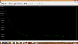
I hadn't tried this before but here is a comparison of the noise from tone control section of Doug Selfs precision preamp with the controls centred. Look at the noise in the critical 4kHz zone (and above and below).
I think you have a combination of things going on here, mainly that super efficient 107db speaker. There is no way you can connect something like this stage via a power amp to something like that and expect it to be silent. It just can't happen (unfortunately).
I think you have a combination of things going on here, mainly that super efficient 107db speaker. There is no way you can connect something like this stage via a power amp to something like that and expect it to be silent. It just can't happen (unfortunately).
Attachments
heureka it works!!
first time i use the 2068.
will test 5532 and tl072 tomorrow.
i've build seperated pcb for,
- psu,
- summer & eq,
- filter
all that with pin connectors onto a strip board.
it is kind of a bus, with
pin1 - Vref
pin2 - Ground
pin3 - Vcc
pin4 - Signal
the signal is from the eq stage, can be taken by any filter stage i'll build in the future.
..or i can put just an output buffer onto it, for fullrange use.
that is true diy fun!!!
")
Yes, it is much quieter now.
But i guess the main failure was somewhere in my construction.
TL072 work well in my new built, too.
But i prefer the NJM2068.
Awesome product for 0.40€ per piece.
Another question looking forward to future projects:
Is the approach of using MFB bandpass filters for subwoofers, evaluated/documented somewhere?
Is it worth looking at bandpass filters for active audio crossovers?
The LM833 is another device that might be worth considering.
I'm afraid I've no idea on the MFB filters beyond starting from zero and searching for info.
Multiple Feedback Bandpass Filter
And probably well worth a read,
The Design of Active Crossovers by Douglas Self
I'm afraid I've no idea on the MFB filters beyond starting from zero and searching for info.
Multiple Feedback Bandpass Filter
And probably well worth a read,
The Design of Active Crossovers by Douglas Self
MFB are popular because they separate Q, from Gain and from Frequency.
They allow you to set Gain independently of Q.
D.Self's book drew my attention to the higher distortion of a high pass MFB that I had never seen in any previous papers on using the MFB.
The low pass MFB does not suffer this extra distortion and thus is ideal as the summing plus filtering stage for the 0.1 bass channel of a x.1 sound system.
amp guru offers this as a stage on his website.
The LM833 is another device that might be worth considering.
i'll possibly try those.
but:
5532 and tl072 cost around 0.25€.
2068 costs about 0.40€.
lm833 available for 0.70€.
i think have to stop climbing that ladder, as the real improvements might be done elsewhere in my equipment.
I'm afraid I've no idea on the MFB filters beyond starting from zero and searching for info.
Multiple Feedback Bandpass Filter
And probably well worth a read,
The Design of Active Crossovers by Douglas Self
i came across those sites a few days ago.
actually it was the esp website that draw my attention towards bandpass filters while reading the article about the graphic eq project.
MFB are popular because they separate Q, from Gain and from Frequency.
They allow you to set Gain independently of Q.
D.Self's book drew my attention to the higher distortion of a high pass MFB that I had never seen in any previous papers on using the MFB.
The low pass MFB does not suffer this extra distortion and thus is ideal as the summing plus filtering stage for the 0.1 bass channel of a x.1 sound system.
amp guru offers this as a stage on his website.
i like the sallen-key topology for its simplicity.
i built a 3rd order mfb lowpass for my home subwoofer.
the project was (and still is) a great success.
as far as i understand the constant Q is a big advantage of the implementation ESP shows in its project.
that kind of stuff definitely draw my attention.
as soon as i found reasonable priced slide pots i'll built that.
i'm afraid that my perf-board struggles might be overstressed with the size of this project.
it is possible that i head into a different direction, using arduinos and digi pots and try to create a kind of interface to control xo-frequencies, eq, Q, ....
this looks like fun, but reaches dimensions of costs where it is hard to argue against dsp stuff.
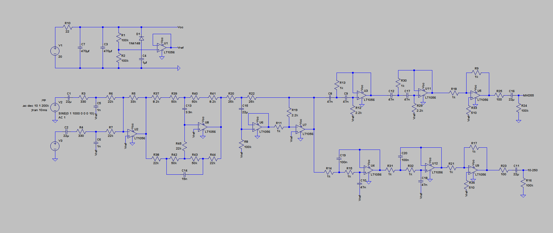
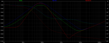
the sim i made looks like this.
green is the xo for 2x 12" subwoofers as it is.
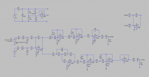
it uses cascaded sallen key filters (4th order) to get ~45Hz and ~125Hz xo-frequencies with Q=0.707.
(this is shown in the last circuit diagram i posted)
blue are two cascaded MFB BPF with Q=0.707, one with f0=60Hz, the other at 100Hz.
green is the curve that caught my attention:
It uses two MFB BPF with Q=1.3, f01=50Hz, f02=115Hz.
Only the -10db gain is holding me back from building it.
Is there a way of adding gain within the filter stages?
Should i simply compensate the attenuation with more gain at the previous summing stage?
If this works in reality, it would be awesome, because of the use of only two opamps.
green is the xo for 2x 12" subwoofers as it is.
it uses cascaded sallen key filters (4th order) to get ~45Hz and ~125Hz xo-frequencies with Q=0.707.
(this is shown in the last circuit diagram i posted)
blue are two cascaded MFB BPF with Q=0.707, one with f0=60Hz, the other at 100Hz.
green is the curve that caught my attention:
It uses two MFB BPF with Q=1.3, f01=50Hz, f02=115Hz.
Only the -10db gain is holding me back from building it.
Is there a way of adding gain within the filter stages?
Should i simply compensate the attenuation with more gain at the previous summing stage?
If this works in reality, it would be awesome, because of the use of only two opamps.
Attachments
It is an inverting stage.
The two resistors at input and feedback control the gain.
Gain = - Rfb/Rin
Fit two input resistors and it becomes a summing stage.
Gain = - Rfb/Rin1 + (-Rfb/Rin2)
If Rin1 = Rin2, then gain = -2Rfb/Rin1
Be careful:- the summing stage can clip because the output signal is double the input signal.
The two resistors at input and feedback control the gain.
Gain = - Rfb/Rin
Fit two input resistors and it becomes a summing stage.
Gain = - Rfb/Rin1 + (-Rfb/Rin2)
If Rin1 = Rin2, then gain = -2Rfb/Rin1
Be careful:- the summing stage can clip because the output signal is double the input signal.
Last edited:
I've retested each section individually just by breaking the chain at stage and injecting the input signal at that point. So here you have four test points, Gain 1 through to Gain 4 and the noise of each stage. Look at the scale in Gain 1 plot. We are in microvolts of noise here.
I built a new version of this, which fits into one enclosure together with the power amp.
This is much more practical for taking it to the outside.
I made an improvement with omitting the treble part of the tone control and put the bass control only into the 'low' signal path.
The power amp i use for this has BTL outputs.
Would inverting the speaker polarity for the woofer be the same as putting an inverting opamp stage in front of the amp channel input?
What do i have to change if i switch to +-9V battery (two batteries with center tap) supply?
(http://www.diyaudio.com/forums/powe...estion-wiring-battery-system.html#post4458600)
Attachments
Yes, reversing the speaker does exactly the same as adding an inverting stage to the audio chain.
To self power the preamp from two batteries you can either leave things as they are and still carry on using the virtual ground. Your circuit is really drawn as a single rail anyway because all signal grounds are referred back to the attery negative, the opamp in the power supply simply providing 'Vref. True virtual ground would see all the audio grounds referred back to Vref... so Vref beomes the point from which all measurements and signals are referenced too.
----------------------------------------------------------------------------------------
With your eight SLA batteries you could connect all in series and take a centre point as ground. That would give plus and minus 24 volts DC. You could then power the preamp from the same batteries but take the preamp supply from the second battery above and below the centre point. That would give a -/+ 24v and -/+ 12v supply all from the same batteries. In that case you would have to convert the preamp to true split rail by dispensing with the opamp and refering all signal grounds to the new battery centre point.
Why are you summing the filtered outputs with U10?
The summed output is available at U2.
Are you aware that U10 will overload when the other opamps are at half maximum signal voltage?
To avoid this potential overload, reduce R26 to 11k. post254 refers.
You have a lot of gain at U2.
For two inputs of 1Vac the U2 output is 1V*33/22 + 1V*33/22 = 3.3Vac = 9.3Vpp
And U10 output is ~18.6Vpp
C1 & C2 could usefully be reduced to 4u7F and then adopt MKT instead of electrolytic.
Last edited:
Why are you summing the filtered outputs with U10?
The summed output is available at U2.
Are you aware that U10 will overload when the other opamps are at half maximum signal voltage?
To avoid this potential overload, reduce R26 to 11k. post254 refers.
You have a lot of gain at U2.
For two inputs of 1Vac the U2 output is 1V*33/22 + 1V*33/22 = 3.3Vac = 9.3Vpp
And U10 output is ~18.6Vpp
I have U10 in there only to check if the 'result' would be a flat frequency response.
I do not build that, it is just for simulation (without speakers).
C1 & C2 could usefully be reduced to 4u7F and then adopt MKT instead of electrolytic.
The film caps i have in stock were simply too big for that build.
With your eight SLA batteries you could connect all in series and take a centre point as ground. That would give plus and minus 24 volts DC. You could then power the preamp from the same batteries but take the preamp supply from the second battery above and below the centre point. That would give a -/+ 24v and -/+ 12v supply all from the same batteries. In that case you would have to convert the preamp to true split rail by dispensing with the opamp and refering all signal grounds to the new battery centre point.
I don't get it completely.
I plan to use them in series with a center tap which would give something around +-50V if fully charged.
That center tap will connect to the audio GND of the source.
I need the same center tap for the preamp, right? (then with the next possible potentials for +-12V (~13V))
- Status
- This old topic is closed. If you want to reopen this topic, contact a moderator using the "Report Post" button.
- Home
- Source & Line
- Analog Line Level
- Designing a noob-preamp (single supply)