Wild guess - both tweeters are maybe fried and their voice coils are stuck in the magnet gaps? I once tested some B&W speakers that turned out to have toasted tweeters and they measured very similarly to the curves you have. When the voice coil is stuck, it can still make some sound, but mostly just a peak.
I'd unwire one of the tweeters and drive it (only) through maybe a 10uF or so capacitor and see if yours have response like that.
I'd unwire one of the tweeters and drive it (only) through maybe a 10uF or so capacitor and see if yours have response like that.
I have the same problem with the tweeter when I test my 2 way speaker. The curve of the tweeter is fine at the beginning of the test but after I repeat the test to the fifth time, the curve will look like that. It will be changed. I guess that the high power of the pink noise at high frequency cause that problem to the tweeter. The tweeter will not sound the same as before (missing high frequency). The other same speaker which I never perform the test the tweeter still sounds good ( before both speakers sound the same). I took another pair and tested one speaker several times and I can see the curve of the tweeter changed. I guess the coil of the tweeter become too hot or the magnetic field of the tweeter motor changed.
I was searching around and found a video on youtube that shows how to check the voice coil https://youtu.be/gTIjFJWh0_E
I tested the tweeter this way and it reads 3.3ohm. This should mean its working ?
I don't have a 10uF capacitor now to test the tweeter alone. Can the woofer be tested alone without the crossover ?
I tested the tweeter this way and it reads 3.3ohm. This should mean its working ?
I don't have a 10uF capacitor now to test the tweeter alone. Can the woofer be tested alone without the crossover ?
Last edited:
I have the same problem with the tweeter when I test my 2 way speaker. The curve of the tweeter is fine at the beginning of the test but after I repeat the test to the fifth time, the curve will look like that. It will be changed. I guess that the high power of the pink noise at high frequency cause that problem to the tweeter. The tweeter will not sound the same as before (missing high frequency). The other same speaker which I never perform the test the tweeter still sounds good ( before both speakers sound the same). I took another pair and tested one speaker several times and I can see the curve of the tweeter changed. I guess the coil of the tweeter become too hot or the magnetic field of the tweeter motor changed.
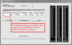
Think sounds weird how this happen. Forgive me if wrong but to end up a broken tweeter after a sweep with REW, it sounds as you probably connect tweeter directly to amp without a high pass XO (use example a 10uF cap as bwaslo suggest in post 61) and then run a impulse train sweep from DC to end frq , if one test tweeters without XO set sweep to a higher start frq than DC, see below.
Attachments
I was searching around and found a video on youtube that shows how to check the voice coil https://youtu.be/gTIjFJWh0_E
I tested the tweeter this way and it reads 3.3ohm. This should mean its working ?
I don't have a 10uF capacitor now to test the tweeter alone. Can the woofer be tested alone without the crossover ?
3,3 ohm sounds reasonable if original being a nominal 4 ohm driver, but if orginal a 8 ohm driver then its fried, guess we don't have reference data what exactly RE value supposed to be. If you run a sweep as bwaslo suggest either connected via a 10uF capacitor to amp or you connect directly and set a higher start frq will reveal if it has broader bandwidth than the plots you had shown until now, as he said not only a "just a peak" would be revealed by this test.
3,3 ohm sounds reasonable if original being a nominal 4 ohm driver, but if orginal a 8 ohm driver then its fried, guess we don't have reference data what exactly RE value supposed to be. If you run a sweep as bwaslo suggest either connected via a 10uF capacitor to amp or you connect directly and set a higher start frq will reveal if it has broader bandwidth than the plots you had shown until now, as he said not only a "just a peak" would be revealed by this test.
Guess I really need to get the capacitor to do this test. This capacitor is connected like in this picture for the high frequency ? So it is essentially a first order crossover ?

picture from Shavano Music Online - First Order Crossover Networks
Guess I really need to get the capacitor to do this test. This capacitor is connected like in this picture for the high frequency ? So it is essentially a first order crossover ?
picture from Shavano Music Online - First Order Crossover Networks
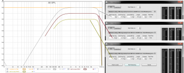
Its fine if you feel most safe using a capasitor for the test, but actual you can spare the money by setting start frq into REW before doing the sweep as shown below. The plot show my DSP engine set to a loop via my soundcard where REW listen in the chain, then a filter is set to replicate a typical plot for a tweeter bandpass 800-18kHz. Grey trace show "Make a measurement" dialog meny have set start frq sweep from down 0Hz and up and therfor in plot one can see the frq energy fade out down at -50dB around 46Hz, but look at brown and gold traced where start frq is set to respective 250Hz and 500Hz you see the sweep send no energy to the driver below that frq point and thereby you can spare your money for the capacitor. Actual its possible to play a music track to a tweeter without XO and without destroying tweeter but it needs to be at very low SPL. If you fear hurting tweeter then set REW start frq to 1000Hz before the sweep and you really safe.
Attachments
Buzzy,
The test is so short think if you have only eletrolytics laying around it doesn't matter nothing will explode in so short a time. Besides do you know you can wire a electrolytic back to back, example two 22uF in series (-/+ wire +/-) replicate a bipolar 11uF.
Hope and look forward see if tweeter can show a broader bandwidth than we seen when feeded from XO network.
Buzzy,
The test is so short think if you have only eletrolytics laying around it doesn't matter nothing will explode in so short a time. Besides do you know you can wire a electrolytic back to back, example two 22uF in series (-/+ wire +/-) replicate a bipolar 11uF.
Hope and look forward see if tweeter can show a broader bandwidth than we seen when feeded from XO network.
I did not know that u can convert a electrolytic back to back to turn it into a bipolar cap. Have been learning alot since I started tinkering with this speaker. Thanks for sharing this info.
.....Have been learning alot since I started tinkering with this speaker.....
Great me too have learned a lot here : )
Little more info regarding back to back config then, it doesn't matter if its (-/+ wire +/-) or (+/- wire -/+) especially not with modern types that typical have isolated non floating metal house that doesn't connect with negative or positive terminal. Also some other rules is when wiring caps serial their value get half and voltage double up, where when paralleling them their value add up and voltage stay same, try use two of same value when serialize them or at least count the summed value will be less the the smallest value. Inside this scheme you free to parallel some than then sits back to back with another parallel set in order to reach your goal, or serialize some than then go parallel to another serial set.
Last edited:
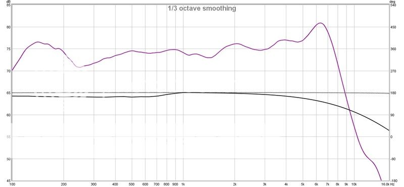
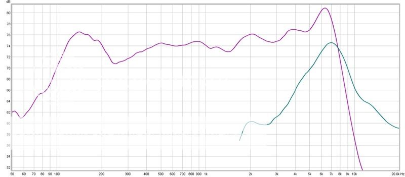
Just got my capacitors to test my mission tweeter and woofer separately. I test both the tweeter and woofer still mounted on the cabinet of the speaker. I hooked them up individually 1 at time for the test. Test was at 0.5 m on axis with tweeter. Amplifier volume kept the same for both woofer and tweeter. Position of mic did not shift for both woofer and tweeter test. These were my results. Mic not sensitive beyond 6Khz.
Woofer
Tweeter
Combined into one graph
Woofer
An externally hosted image should be here but it was not working when we last tested it.
Tweeter
An externally hosted image should be here but it was not working when we last tested it.
Combined into one graph
An externally hosted image should be here but it was not working when we last tested it.
Last edited:
I maybe a newb to this sort of thing and getting along so-so,
But why do you keep trying to measure with a known defective microphone how can anyone help you interperate the results correctly.Or rather come to a conclusion accurately when one is using inaccurate equipment.
Have you disconected the tweeter or one side of it from the crossover and measured it with a multimeter?
But why do you keep trying to measure with a known defective microphone
how can anyone help you interperate the results correctly.Or rather come to a conclusion accurately when one is using inaccurate equipment.Have you disconected the tweeter or one side of it from the crossover and measured it with a multimeter?
The microphone is not defective. Its just not sensitive beyond 6Khz. For my use, I am just bothered about the huge dip in frequency response at the 2.8Khz. I don't know y there is such a huge dip of 10 to 12 dB at the crossover frequency. If u see post #48 where I measured both the tweeter and woofer individually with the crossover attached I had the dip in freq. But if I measured just the woofer here without the crossover there, is no dip in freq.
In the meantime I am still trying to get another mic for the higher frequencies. When I was running the freq sweep I can hear the tweeter. Its just much lower in loudness than the woofer.
In the meantime I am still trying to get another mic for the higher frequencies. When I was running the freq sweep I can hear the tweeter. Its just much lower in loudness than the woofer.
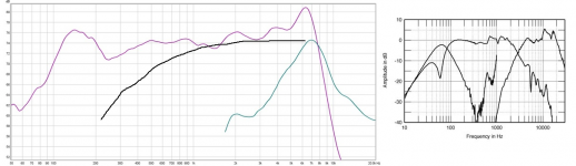
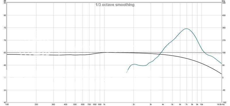
Hi Buzzy it doesn't look good and points to what bwaslo described at post 61 that drivers are defect. A guess is tweeter should have looked ala below black trace up to 6kHz point where microphone falls off but it didn't, even if capasitor had too low a value it would have been a softer raising high pass slope and guess also you used a 10uF as bwaslo recommended.
Attachments
Hi Buzzy it doesn't look good and points to what bwaslo described at post 61 that drivers are defect. A guess is tweeter should have looked ala below black trace up to 6kHz point where microphone falls off but it didn't, even if capasitor had too low a value it would have been a softer raising high pass slope and guess also you used a 10uF as bwaslo recommended.
I used 22uF capacitor. The woofer is still usable ?
Last edited:
Wild guess - both tweeters are maybe fried and their voice coils are stuck in the magnet gaps? I once tested some B&W speakers that turned out to have toasted tweeters and they measured very similarly to the curves you have. When the voice coil is stuck, it can still make some sound, but mostly just a peak.
I'd unwire one of the tweeters and drive it (only) through maybe a 10uF or so capacitor and see if yours have response like that.
If the voicecoil is stuck can it be repaired ?
I used 22uF capacitor.
Okay that is good for the test but sorry because tweeter is not alright then.
Have you had a party or so where they been running close at distortion level for longer times you can remember is the reason for it.
Hope it's possible to get the spare part somewhere new or used or even just get the voice coil so XO components don't need to be retuned.
If the voicecoil is stuck can it be repaired ?
Don't think so, had sometimes repaired tweeters that had got a shock from crazy high wattage overload input, they often burn copper wire outside the coil enroute to soldering terminal and is repairable with some patience when repairing. But in that case their error sign is they say nothing at all after the overload shock, where yours have probably cooked lacquer on copper wire where its coiled up and that boiled lacquer is now stuck in gap hindering voice coil free movement.
Nowadays you can probably get some very cheap very good tweeters from other brands that can do the job but you will then need microphone support that is okay to tweak XO component values for new different tweeter type.
If faceplate on tweeter is possible to remove you could do that and inspect voice coil health, maybe upload a picture of how it looks.
- Status
- This old topic is closed. If you want to reopen this topic, contact a moderator using the "Report Post" button.
- Home
- Loudspeakers
- Multi-Way
- Crossover tuning