Here`s the nest, works better than it looks......
Did you try to remove the 3 inputs résistors before the tDA chip (or just desolder one side of each resistor and bypass it with 3 thin copper wires ?
You should
") It's a filter where the caps are below the other above pcb...
It's a filter where the caps are below the other above pcb...How bad is the DC offset on a PCM1704?
They vary, one of mine was 2mV the other was 10mV, just use the 20kohm trimpot on pin 1 and 8 one of the stacked 844's and you'll get very stable +- 1mV dc offset.
Cheers George
PCM1704
Thanks George, Good information to have. Need to make a parts order so it will be a week or 2 to get it together.They vary, one of mine was 2mV the other was 10mV, just use the 20kohm trimpot on pin 1 and 8 one of the stacked 844's and you'll get very stable +- 1mV dc offset.
Cheers George
It's alive.... Tweaking it since last Thursday. Resistor I/V = 25 Ohms. SRPP ECC86/ 2SK170.... Results. Best DAC to date. So my question is with 0-8 mA output, would that seem to be to much for the AD844?
I like the heatsink on the 1541A. You could go one further and connect this to either signal common or hard ground, depending, this could be the same.
L.H
Did you try to remove the 3 inputs résistors before the tDA chip (or just desolder one side of each resistor and bypass it with 3 thin copper wires ?
You should
Yes, I removed the 22P caps and reduced the resistors from 220R to 22R - to me no audible benefits even though waveforms look much better and theory tells so.
Regards
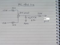
If it is this drawing you mean, it does not say 5VAC. It says 5VA which to me is 5VAnalog (power)
My bad. That make sense now!
Thanks
For a different application, can I use +/-12 and change the resistor values?Yes for clarity it should have labeled + & - 5vdc from the "analogue" power supply, not power from the dirty digital side of things.
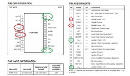
In the case of the PCM1704K dac chip, the green not the red. (attached)
Cheers George
LTspice simulation seems to be ok.
I'm not sure there's any other concerns.
Re this post http://www.diyaudio.com/forums/digital-source/227677-using-ad844-i-v-59.html#post4417322 I'm sure it can just ask Abraxilito if he can reconfigure his circuit for +-12vdc.
Cheers George
Cheers George
Changed resistor at pin5 from 18K to 10K and capacitor from 47P to 100P.
Changed 0.1uF to 47nF
You are right, we all take inspiration from many places and do I own thing.
Now, may I ask please that you try this and trust me on it, a little test that will be part of an experiment soon on another thread not yet established.
Change the 47nF to 0.33uF - this is directly across the phases of the DAC. That is all. I know that is a large value change, but the effect on the response has been modeled.
Lesser point, consider reduce Pin 5 cap down to 33nF, but 47nF would do OK, to compensate for what 0.33uF does, that that is just a finer point.
You may hear something you didn't expect.
Cheers, Joe
Here`s the nest, works better than it looks......
As long as you know it is following a schematic, it is OK to trial
construction like this.
A famous designer Bob Pease pictured here
https://books.google.co.nz/books?id...ce=gbs_ge_summary_r&cad=0#v=onepage&q&f=false
with many more wires than yours.
Once you know it works well, another approach is get to know surface mount components which can help.
Heatsink ground?
Just curious... What is the benefit to grounding the heatsink? Noise suppression?I like the heatsink on the 1541A. You could go one further and connect this to either signal common or hard ground, depending, this could be the same.
L.H
You are right, we all take inspiration from many places and do I own thing.
Now, may I ask please that you try this and trust me on it, a little test that will be part of an experiment soon on another thread not yet established.
Change the 47nF to 0.33uF - this is directly across the phases of the DAC. That is all. I know that is a large value change, but the effect on the response has been modeled.
Lesser point, consider reduce Pin 5 cap down to 33nF, but 47nF would do OK, to compensate for what 0.33uF does, that that is just a finer point.
You may hear something you didn't expect.
Cheers, Joe
Changing 47N to 330N seems resonable to me, but what`s the reason for changing the cap on pin5 from 47P(100P) to 33N or 47N? Isn`t that a very early rolloff? or did you mean 33P or 47P?
Regards,
Jürgen
Changing 47N to 330N seems resonable to me, but what`s the reason for changing the cap on pin5 from 47P(100P) to 33N or 47N? Isn`t that a very early rolloff? or did you mean 33P or 47P?
Regards,
Jürgen
Hi Jurgen
My mistake, yes 33pF or 47pF.
Otherwise it would cause huge in-band roll-off. The change to 330nF should cause some marginal roll-off at 20KHz - but this is something delta-sigma DACs actually like and I predict you will hear that.
Cheers, Joe
-
Is it possible to take the Voltage (or curent ?) signal from the dac chip (after the resistor for I/V or before - if I/V is on the other board) to an other board with its own layout for the AD844s ? (assuming the links (signal & ground) between the boards are as short a possible!
I think about a standalone board with 2 or more ad844 for experiments from many dac chips : BB 1704 (topic of George), but also TDA1541, AD1862, etc !
Is it possible to split the grounds with just a wire without to much problems ?
I think about a standalone board with 2 or more ad844 for experiments from many dac chips : BB 1704 (topic of George), but also TDA1541, AD1862, etc !
Is it possible to split the grounds with just a wire without to much problems ?
Hi Jurgen
My mistake, yes 33pF or 47pF.
Otherwise it would cause huge in-band roll-off. The change to 330nF should cause some marginal roll-off at 20KHz - but this is something delta-sigma DACs actually like and I predict you will hear that.
Cheers, Joe
-
Thanks for the clarification. I just have finished a Firstwatt F1J clone. For the extensive listening with my Elsinore Mark5 that will follow the next weeks l intend to implement your suggestions in my Philips CD723 (in future maybe a contribution to the thread dealing with your trans-amp or with the Elsinore?)Regards, Jürgen
Hi Guys
A little off topic. With George's wonderful circuit, I was wondering if I could adapt the gain & buffer stage into a UCD 400 OEM module. I don't know much about OP amps but I guess all that is need ed is to tweak the AD844 for higher voltage gain. Would appreciate you views
Thanks
A little off topic. With George's wonderful circuit, I was wondering if I could adapt the gain & buffer stage into a UCD 400 OEM module. I don't know much about OP amps but I guess all that is need ed is to tweak the AD844 for higher voltage gain. Would appreciate you views
Thanks
- Home
- Source & Line
- Digital Line Level
- Using the AD844 as an I/V