Good stuff and things
")
Oh heck yes , one of these little 8th order boxes would be great for a small music system , or a herd of them could work for a large system =) Cost effective and LOUD
By the way Freddi , i have cut out the wings for my K-slot on the Karlflex prototype, i am waiting for some glue to dry then i am going to attach the wings, it is pretty basic but will look cool ..... It is just a straight slot about 2.5 inches across at the top coming all the way down to where the driver's cone is and it opens up from there (using 55 degree angles) , no radius just straight cuts on this first try , i suspect it will have to be opened up more ........ I will be doing some listening tests and will post the measurements over in the other discussion tonight or tomorrow ...
I am working on getting the original Sun recordings right nowbesides the typical original Sun recording collections which include "Get Rhythm", I like the following album a lot http://www.amazon.com/Sings-Ballads-True-West-Johnny/dp/B00006GO9E
there oughta be some applications for a punchy/loud 8th order BP
Oh heck yes , one of these little 8th order boxes would be great for a small music system , or a herd of them could work for a large system =) Cost effective and LOUD
By the way Freddi , i have cut out the wings for my K-slot on the Karlflex prototype, i am waiting for some glue to dry then i am going to attach the wings, it is pretty basic but will look cool ..... It is just a straight slot about 2.5 inches across at the top coming all the way down to where the driver's cone is and it opens up from there (using 55 degree angles) , no radius just straight cuts on this first try , i suspect it will have to be opened up more ........ I will be doing some listening tests and will post the measurements over in the other discussion tonight or tomorrow ...
looking forwards to your K-slot measurements and impressions
OK , it is posted in the Transflex discussion
I hope you don't mind the quote ..... hehehe
Here they are
Mr Do it Yourself ,
Take a look at posts #34, #39, #42, and #59 ... They contain graphs for the standard 8th order triple reflex like the schematic you posted above ....
Then the graphs in post #7 are from a variant of that same design where the chambers/ports are just stretched out to make simple resonant pipe sections ...
how about the basic triple reflex?
Mr Do it Yourself ,
Take a look at posts #34, #39, #42, and #59 ... They contain graphs for the standard 8th order triple reflex like the schematic you posted above
.... Then the graphs in post #7 are from a variant of that same design where the chambers/ports are just stretched out to make simple resonant pipe sections ...
DCR/ABC Another one of David's new modes .... PA-310
I tried the Dayton PA-310 in another one of David's new and interesting Hornresp modes ... The ABC (DCR) mode ...
I used the classic DCR configuration with all three ports being the same dimensions .... All ports are 48cm long and have 200cm sq cross-sectional-area ..... These large ports keeps the air particle velocity nice and low ...
The design is 120 liters net (internal air space) with the two chambers taking up 90 liters (a 30/60 split) and the ports taking up the remaining 30 liters ...
Looks really good for 29v (roughly 100w) of input power , with the way this design controls cone movement it should be possible to actually drive upwards of 38v into this system which should be pushing very close to 120db output levels down to 40hz (at one meter in halfspace)...
Bandwidth should be excellent since this is a direct radiating arrangement , there would only be a little dip at 80hz but from that point on up it should conform to the high frequency limits of the driver itself which is around 2khz before cone breakup and beaming become a big issue (which is actually really good for a budget 12) .... Disregard all of the squiggle and ripple that you see in the high frequency region of the Hornesp graph , HR is only really meant to model low frequencies, the higher frequencies will actually be very smooth compared to what you see in the graph, in fact it would be similar to the high frequency response you would get with a standard ported bass-reflex cabinet ..
This DCR/ABC design could be a very simple and effective solution for the Dayton PA-310
An externally hosted image should be here but it was not working when we last tested it.
An externally hosted image should be here but it was not working when we last tested it.
An externally hosted image should be here but it was not working when we last tested it.
An externally hosted image should be here but it was not working when we last tested it.
cool - didn't realize it does DCR - may I see the input window? IIRC (?), the notch can be lessened/removed by damping the inner port but there goes some of the excursion reduction - a box like this could be nice with a coax
Freddi ,
Yes of course! Here is the input window
An externally hosted image should be here but it was not working when we last tested it.
In different simulations (with other software) i have had some luck by altering the Q of the resonances generated by the parasitic chamber ... If the resonance is made a little less sharp , softened, with a little more spread it can actually improve excursion control while also being a remedy for the DCR "dip" ..... It is the reason why i added a little bit of stuffing into my parasitic labyrinth section of the Karlflex prototype , but i placed the stuffing in a spot where it wouldn't choke the airflow ...
In retrospect i think that using a pipe section (offset driven by the interchamber vent) as the parasitic portion of the box is the way to go because it leaves a perfect spot for adding stuffing without degrading performance of the box at FB ...... You can see this sort of offset driven parasitic pipe section design built into the MTM-DCR-TL towers that we made for my friend, i posted the sketch of it just the other day in the Transflex discussion .......... That offset parasitic pipe design was fully experimental, but worked out really well for us
Last edited:
can one get a good sounding K using 2:1 rear chamber proportions and DCR tuning?
I've had 18" 2-ways sound reasonably good - better than little FR when using a Smith DSH on top, or K-internally - I'd like to have a new K-type/flex which reaches about as deep as the excellent Karlsonator
look a few inches above the woofer in this picture and you'll see where the K-tube normally mounts - it was good on opera,
percussion, etc.
this shorter coupler normally ran an 18 - this pic is with a 15" Altec - the 18 which sounded pretty crappy
as a direct radiator subjectively improved in the cavity which is about like a big K12. When that upper gap
was narrowed to ~3/4" , the sound which was very good started sounding constipated - something like a Klipschorn's bass
section = ugh. Its case by case - some couplers/speakers could sound excellent with a 1/16" starting gap.
If the upper narrow slit is blocked on the tall coupler shown above, then it sounds like there's "less highs" and
subjectively slower.
I've had 18" 2-ways sound reasonably good - better than little FR when using a Smith DSH on top, or K-internally - I'd like to have a new K-type/flex which reaches about as deep as the excellent Karlsonator
look a few inches above the woofer in this picture and you'll see where the K-tube normally mounts - it was good on opera,
percussion, etc.
An externally hosted image should be here but it was not working when we last tested it.
this shorter coupler normally ran an 18 - this pic is with a 15" Altec - the 18 which sounded pretty crappy
as a direct radiator subjectively improved in the cavity which is about like a big K12. When that upper gap
was narrowed to ~3/4" , the sound which was very good started sounding constipated - something like a Klipschorn's bass
section = ugh. Its case by case - some couplers/speakers could sound excellent with a 1/16" starting gap.
If the upper narrow slit is blocked on the tall coupler shown above, then it sounds like there's "less highs" and
subjectively slower.
An externally hosted image should be here but it was not working when we last tested it.
Last edited:
Rambling about my recent experience , and contemplating possibilities
Freddi ,
It can be done .... It would be a tri-chamber Karlson ABC hybrid! It is basically what i tried to accomplish with this Tri-chamber Karlflex .... It seems to me that it would be a quasi-8th order if not truly 8th order because of the amount of effective chamber/vent sets all providing their own significant resonances within the working range ... You count up the orders as 2 orders per chamber/vent set and 2 for the driver itself ...
You are right, one of the vents has to be compensated because it will be placed behind the K-aperture which provides extra loading ............ After some experimentation with different arrangements in Akabak i decided to put the main vent (referring to the HR schematic it would be the vent from chamber 1) behind the aperture because the response looked much more desirable that way............. Then the other vent (The parasitic chamber's vent) is direct radiating like a normal DCR/ABC .......
Of course the Karlflex example is a little different than the HR schematic because the main chamber has a long aspect ratio and the driver is offset within that pipe section instead of the box-like chamber in the HR schematic ....
I ran into a few problems when simulating this design though ..... I found that the dip around the parasitic resonant frequency does not improve when a front chamber resonance is added to the system, the dip just stays suppressed so it creates a terrible response curve if the front chamber's resonance is tuned low .... For example, you could have an FB of lets say 45hz, then a parasitic resonance between 80 to 85hz and a front chamber resonance of 180hz , but that would result in a dip around 85hz and a large hump in response centered around 180hz , not so good....... So that is one of the reasons why i made the front chamber so small in the Tri-Chamber Karlflex box putting it's resonance up to around 500hz (or 400hz with the Freddi-mod cavity , which works well) ........
Another problem that i ran into is the interference between the front chamber resonance and the main pipe's 5th and 7th harmonics creating radical dips and peaks if those resonances are located in the same range ..... So again it just worked out best if the front chamber's resonance is placed above those more prominent odd harmonics, of course i suppose this wouldn't apply if the system were helmholtz based instead of quarter wave ...
For a 2:1 back/front chamber ratio the design would have to be worked out in Akabak , Maybe something with a large or extended Freddi-mod sort of cavity? , or a very tall aperture and front chamber driven in the middle somewhere? Making something like this work along with the ABC/DCR feature can be tricky .......
There could be benefits though , as you say some drivers that sound crummy as direct radiators sound much better when behind A K-slot .... Xrk mentioned the diffraction lens effect that the K-slot can have upon drivers that would normally get beamy and harsh or ugly sounding on-axis while lacking clarity off-axis at higher frequencies, according to Xrk's measurements the K-slot remedies these dispersion issues ...
can one get a good sounding K using 2:1 rear chamber proportions and DCR tuning?
I've had 18" 2-ways sound reasonably good - better than little FR when using a Smith DSH on top, or K-internally - I'd like to have a new K-type/flex which reaches about as deep as the excellent Karlsonator
look a few inches above the woofer in this picture and you'll see where the K-tube normally mounts - it was good on opera,
percussion, etc.
this shorter coupler normally ran an 18 - this pic is with a 15" Altec - the 18 which sounded pretty crappy
as a direct radiator subjectively improved in the cavity which is about like a big K12. When that upper gap
was narrowed to ~3/4" , the sound which was very good started sounding constipated - something like a Klipschorn's bass
section = ugh. Its case by case - some couplers/speakers could sound excellent with a 1/16" starting gap.
If the upper narrow slit is blocked on the tall coupler shown above, then it sounds like there's "less highs" and
subjectively slower.
Freddi ,
It can be done .... It would be a tri-chamber Karlson ABC hybrid! It is basically what i tried to accomplish with this Tri-chamber Karlflex .... It seems to me that it would be a quasi-8th order if not truly 8th order because of the amount of effective chamber/vent sets all providing their own significant resonances within the working range ... You count up the orders as 2 orders per chamber/vent set and 2 for the driver itself ...
You are right, one of the vents has to be compensated because it will be placed behind the K-aperture which provides extra loading ............ After some experimentation with different arrangements in Akabak i decided to put the main vent (referring to the HR schematic it would be the vent from chamber 1) behind the aperture because the response looked much more desirable that way............. Then the other vent (The parasitic chamber's vent) is direct radiating like a normal DCR/ABC .......
Of course the Karlflex example is a little different than the HR schematic because the main chamber has a long aspect ratio and the driver is offset within that pipe section instead of the box-like chamber in the HR schematic ....
I ran into a few problems when simulating this design though ..... I found that the dip around the parasitic resonant frequency does not improve when a front chamber resonance is added to the system, the dip just stays suppressed so it creates a terrible response curve if the front chamber's resonance is tuned low .... For example, you could have an FB of lets say 45hz, then a parasitic resonance between 80 to 85hz and a front chamber resonance of 180hz , but that would result in a dip around 85hz and a large hump in response centered around 180hz , not so good
....... So that is one of the reasons why i made the front chamber so small in the Tri-Chamber Karlflex box putting it's resonance up to around 500hz (or 400hz with the Freddi-mod cavity , which works well) ........Another problem that i ran into is the interference between the front chamber resonance and the main pipe's 5th and 7th harmonics creating radical dips and peaks if those resonances are located in the same range ..... So again it just worked out best if the front chamber's resonance is placed above those more prominent odd harmonics, of course i suppose this wouldn't apply if the system were helmholtz based instead of quarter wave ...
For a 2:1 back/front chamber ratio the design would have to be worked out in Akabak , Maybe something with a large or extended Freddi-mod sort of cavity? , or a very tall aperture and front chamber driven in the middle somewhere? Making something like this work along with the ABC/DCR feature can be tricky .......
There could be benefits though , as you say some drivers that sound crummy as direct radiators sound much better when behind A K-slot .... Xrk mentioned the diffraction lens effect that the K-slot can have upon drivers that would normally get beamy and harsh or ugly sounding on-axis while lacking clarity off-axis at higher frequencies, according to Xrk's measurements the K-slot remedies these dispersion issues ...
almost a decade since I posted some Z of the little 18"K with and without the upper front 20 liter cavity
Coupled cavity peak vs Z in Karlson type - ping Moray - freddyi - High Efficiency Speaker Asylum
sorry for the two different woofers - I may not have data anymore with just one woofer
no extra cavity
20 liter cavity added to top of front chamber
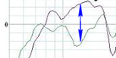
effect upon frequency response - I probably could have "pointed" the mic on a lobe to
have gotten somewhat less drop as F went up
Coupled cavity peak vs Z in Karlson type - ping Moray - freddyi - High Efficiency Speaker Asylum
sorry for the two different woofers - I may not have data anymore with just one woofer
no extra cavity
An externally hosted image should be here but it was not working when we last tested it.
20 liter cavity added to top of front chamber
An externally hosted image should be here but it was not working when we last tested it.
effect upon frequency response - I probably could have "pointed" the mic on a lobe to
have gotten somewhat less drop as F went up
An externally hosted image should be here but it was not working when we last tested it.
Last edited:
Originally Posted by freddi
I'd like to see someone sim Karlson type with ABEC
Don't hold your breath
Karlson's K12 (1954) and X15 (1965) couplers had around 13 cubic inches front chamber volume per square inch of cone area ~0.6 cubic foot for K12, ~ 1 cubic foot for X15. K15 had a bit over 2 cubic foot front chamber. How should one size the front chamber for best distribution of overall effects? In Karlson's originals, the baffle was tilted 20-30 degrees back from an upright perpendicular.
X15 was a good idea when it moved to the internal K-tube - subjectively "fast" - something like a plate lens
X15 was a good idea when it moved to the internal K-tube - subjectively "fast" - something like a plate lens
An externally hosted image should be here but it was not working when we last tested it.
Last edited:
Freddi ,
About post #72
Your cavity mod made a massive amount of difference here .... Lowered FB and lowered front chamber/aperture resonance ..... In the first two examples it looks like it lowered the front chamber resonance by 50hz! and the FB on that comparison is shifted by as much as 20hz if i am reading those correctly ........ If you can find that comparison using the same driver i would really like to look at it
In the third example of post #72 it extended bandwidth, flattened response and improved the bass extension, very nice!
Hi guys, which version of Hornresp is this? I'm interested in the parallel bandpass with the series outer chamber that boosts the top end roll off.
The trouble is, I can't see a trivial way that the outer chamber affects the tunings of the inner chambers.
Hi Tim !
All of the newest versions of David's Hornresp has these modes built in, you just have to hold down the CTRL key while clicking through the modes ...
Which design in particular are you wishing to build? Let us know which post it was featured in ..
- Status
- This old topic is closed. If you want to reopen this topic, contact a moderator using the "Report Post" button.
- Home
- Loudspeakers
- Subwoofers
- Anyone ever attempted an 8th order bandpass?