Gain question
Hi
I came across this thread a couple of months ago. It caught my attention right way, as I’ve build both the B1 buffer, the BOZ and the Jfet BOZ preamps with good results.
I want to build 8 mono BF862 buffers (4 stereo) for an active filter just as member njepitt has done. I have the Salas BIB voltage regulators which I plan to use as PSU.
From post #80 of this thread (http://www.diyaudio.com/forums/pass-labs/146310-bf862-preamp-8.html ) I will dimension the regulators this way:
The positive regulator will set to 24.6V and 160mA (plus 100mA spare current for the regulator).
The negative regulator will set to -4.6V and 80mA (plus 100mA spare current for the regulator).
I have a question about the gain. Is it possible to increase the gain to 10 dB (3.16 times) by adjusting the value of either R1 or R5?
If Voltage gain = Rdrain/Rsource = R1/R5 = 1000/470 = 2.1 ≈ 6dB
Then here are some possible solutions:
Case 1 increase the total resistance: R1 = 1500 and R2 = 470 => 1500/470 = 3.16 ≈ 10 dB
Case 2 decrease the total resistance: R1 = 1000 and R2 = 330 => 1000/330 = 3.0 ≈ 10 dB
Case 3 keep the total resistance the same: R1 = 1100 and R2 = 360 => 1100/360 = 3.1 ≈ 10 dB
Will either one work, and will it change the current of the buffer?
Thank you for the great work")
Hi
I came across this thread a couple of months ago. It caught my attention right way, as I’ve build both the B1 buffer, the BOZ and the Jfet BOZ preamps with good results.
I want to build 8 mono BF862 buffers (4 stereo) for an active filter just as member njepitt has done. I have the Salas BIB voltage regulators which I plan to use as PSU.
From post #80 of this thread (http://www.diyaudio.com/forums/pass-labs/146310-bf862-preamp-8.html ) I will dimension the regulators this way:
The positive regulator will set to 24.6V and 160mA (plus 100mA spare current for the regulator).
The negative regulator will set to -4.6V and 80mA (plus 100mA spare current for the regulator).
I have a question about the gain. Is it possible to increase the gain to 10 dB (3.16 times) by adjusting the value of either R1 or R5?
If Voltage gain = Rdrain/Rsource = R1/R5 = 1000/470 = 2.1 ≈ 6dB
Then here are some possible solutions:
Case 1 increase the total resistance: R1 = 1500 and R2 = 470 => 1500/470 = 3.16 ≈ 10 dB
Case 2 decrease the total resistance: R1 = 1000 and R2 = 330 => 1000/330 = 3.0 ≈ 10 dB
Case 3 keep the total resistance the same: R1 = 1100 and R2 = 360 => 1100/360 = 3.1 ≈ 10 dB
Will either one work, and will it change the current of the buffer?
Thank you for the great work
for active filters, one usually finds excess gain to be the problem.
One could use the classic equal value S&K filters and a bit of gain to set the Q.
Cascaded filters have even more gain.
Because of that extra gain to set the Q values, many Builders adopt the Unity Gain S&K.
Due to the unequal values for components and thus the need for careful matching, this compromise is seen as the lesser evil in return for the Unity Gain.
Adding gain to a an active filter is rare.
Self and Duncan both showed complex active filters and both incorporated gain attenuation at the input to help with controlling the maximum signals inside the crossover.
Think again.
Hi sismik.... Will either one work...
This will work:
keep +V at about 24V
make -V = -3.6V
source resistor = 360R
drain resistor = 1k2
That will keep the Id at the same level (10mA) and give you the gain you want.
When calculating the gain you have yo take into account the intrinsic source resistance of the JFET (1/gm) which is about 25R here.
sismik,
there is an easier way to make this pre (see attached schematic).
That way we don't need the negative PS anymore and the gain is easily adjusted by changing only the value of R3 (in reasonable range: from 100R for 17dB gain to 470R for 6dB gain).
Of course, this demands the use of an input cap (C1) but since it's of small value (47-100 nF) it's easy to fit the good one (WIMA MKP10 or whatever one likes).
Attachments
Juma.
Could you remind me of the formula for predicting the equivalent internal source impedance of Q2?
I assume that we add this internal impedance to R3 to then find the ratio of R5R3+Rint) to see the gain estimate.
Does R2 affect the gain?
Is R4 some kind of bootstrap (+ve feedback)?
How do I turn off the frown? which should have been a colon.
Someone showed me how a few weeks ago !
Found it. tick box disable smilies in text.
Could you remind me of the formula for predicting the equivalent internal source impedance of Q2?
I assume that we add this internal impedance to R3 to then find the ratio of R5
R3+Rint) to see the gain estimate.Does R2 affect the gain?
Is R4 some kind of bootstrap (+ve feedback)?
How do I turn off the frown? which should have been a colon.
Someone showed me how a few weeks ago !
Found it. tick box disable smilies in text.
Last edited:
AndrewT.
You don't stop to amaze me. You keep asking basic questions all the time and fail to understand simplest stuff but that doesn't stop you from "lecturing" scared newbies allthough you really know less than most of them, it's just your arrogant pose that makes them think that you actually know what are you talking about...
So not for you, but for those who will actually make something:
1. & 2. post #344, last sentence.
3. R2 is in the source circuit, so it does affect the gain.
4. R4 sets the gate reference for Vgs of the JFET. When R4 is connected that way, only R2 determines the Vgs of the Q2 but R3 still degenerates the Q2's source and affects the gain that way. That's why there is a positive voltage on the gate and we have to use the input cap. Of course, the source is more positive than the gate (Id x (R3 + R2) vs. Id x R3) so the JFET is correctly polarized this way.
Last edited:
AndrewT.
You don't stop to amaze me. You keep asking basic questions all the time and fail to understand simplest stuff but that doesn't stop you from "lecturing" scared newbies allthough you really know less than most of them, it's just your arrogant pose that makes them think that you actually know what are you talking about...
Good answer Juma
With the posts now exceeding 350, was wondering if anyone took the time to read section 7.4 of Bob Cordell's "Designing Audio Power Amplifiers" -- he shows how to design floating VAS with unipolar JFETS. The idea is further developed in his "Vinyl Trak" preamplifier in Linear Audio 5.
No need for that. Tested it few years ago - looks interesting, but sounds mid-fi. Go sell books and magazines elsewhere...... was wondering if anyone took the time to read section 7.4 of Bob Cordell's "Designing Audio Power Amplifiers" ...
Go sell books and magazines elsewhere...
"Badges, we ain't got no badges, we don't need no stinkin' badges". (Apologies to John Huston)
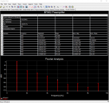
That was fast build and measure... Oh wait !
No, it's just a malevolently adjusted simulation...
I'll show you mine, if you'll show me yours.
I don't do thd measurements .
If you did, you would observe that THD% is, somewhat, a function of the bias voltage.
I have built this preamplifer...
No need for that, although bias voltage is not the only parameter that influences the end result and the THD will not tell you much about the way it reproduces music (yeah, music, not single sinusoidal tones).If you did, you would observe that THD% is, somewhat, a function of the bias voltage....
Ears are quite sensitive to load line optimization and that's easy to check with a simple circuit like this.
I'm one of those funny people that build preamps and amps exclusively to listen to the music. Numbers don't impress me although they are not meaningless. Still, i find "designing by ear" process far more enjoyable and effective.
I don't need to prove anything. I know this little preamp sounds good and few dozens people (that I know of) which built it confirmed that. I don't sell anything, I don't have to take care of market trends or what customers want. I just do what I like and when I'm happy with the results I share them here.
- Home
- Amplifiers
- Pass Labs
- BF862 Preamp