Like I said, a little imagination goes a long way. Even my great grandmother understood what I was saying.
You I can understand, but Jan coming from a country of legalised green stuff I thought would see it, maybe he just hasn't read the thread to understand what I was getting at.
Cheers George
You I can understand, but Jan coming from a country of legalised green stuff I thought would see it, maybe he just hasn't read the thread to understand what I was getting at.
Cheers George
Last edited:
Pedja Discrete diamond I/V

Hi George, Pedja's discrete circuit is in my experience thermally sensitive and yes a cap seems to at least isolate this small variation from the load. I noted your comment about the BUF03 with the AD844. Yes. I hear a little thickness and slight lack of focus with the triple stack. The discrete circuit with the BUF03 is quite clean clear and dynamic. Simply a different sound altogether. It could be a case where the BUF03 simply isn't optimum for the AD844. I still enjoy the triple stack + BUF03. However in critical listening situations I prefer the Pedja discrete + BUF03. The cap in this case is a NOS Russian PIO of about 0.1 uF. I tried a number of caps and that was the best. YMMV I am considering a run of the boards for the discrete circuit, it is that good.I was told by those that have used this "Pedja Rogic"!!!! circuit that an output coupling cap is needed, as the dc offset for them was way out of the nulling's circuit range of adjustability. Not to mention extra noise as well they got on either output.
And the output from TZ is way to high to drive anything external direct, unless a buffer, active or transformer is use.
Cheers George
Here is an alternative to stacking, in fact it may well be equal to stacking up to ten 844s.
George can still take the output from Tz Pin 5.
You also have the option of adding DC nulling as per datasheet. Note you can null both Tz and final output, but there will be some mV difference, so choose one or the other. Also, the 2SK170 current source also affects the DC point.
It can also be used with OPA-660 and OPA-860 - note then the rails need to be +/- 5V.
While the above is a suggested schematic, I have used variations of this in the past.
Cheers, Joe
PS: If anybody builds this and makes necessary adjustment, I can amend this schematic as it loads of my website - I can can update / delete / etc at any time.
.
Hi Joe,
Thank you for the shematic,
Does the 100k shunt resistor is needed at the output with no DC blocking cap ? Is it possible to avoid it ?
regards
Hi George, Pedja's discrete circuit is in my experience thermally sensitive and yes a cap seems to at least isolate this small variation from the load. I noted your comment about the BUF03 with the AD844. Yes. I hear a little thickness and slight lack of focus with the triple stack. The discrete circuit with the BUF03 is quite clean clear and dynamic. Simply a different sound altogether. It could be a case where the BUF03 simply isn't optimum for the AD844. I still enjoy the triple stack + BUF03. However in critical listening situations I prefer the Pedja discrete + BUF03. The cap in this case is a NOS Russian PIO of about 0.1 uF. I tried a number of caps and that was the best. YMMV I am considering a run of the boards for the discrete circuit, it is that good.
Hi Torchwood, yes seeing your using the TDA1541A which has 3 to 4 times the output current (4.6mA) of my PCM1704k (1.2mA) I'm not surprised you prefer 3 stack 844 I/V, in fact I think it could need 4 stack, as Mick Meloney of Supratek found out with his TDA1541 setup!
Cheers George
Last edited:
Hi Joe,
Thank you for the shematic,
Does the 100k shunt resistor is needed at the output with no DC blocking cap ? Is it possible to avoid it ?
regards
It was there in the original circuit, no it is not required.
.
JOE R 844 No stack circuit
I refer to the schematic posted by Joe.
I intended for use with TDA 1541.
I have 4 questions :
What is the value of VR1?
This is to null the open dc ?
ALT stands for what?
The neg power input for the Ad 844 will be ground?
thanks
kp93300
I refer to the schematic posted by Joe.
I intended for use with TDA 1541.
I have 4 questions :
What is the value of VR1?
This is to null the open dc ?
ALT stands for what?
The neg power input for the Ad 844 will be ground?
thanks
kp93300
Attachments
I refer to the schematic posted by Joe.
I intended for use with TDA 1541.
I have 4 questions :
What is the value of VR1?
This is to null the open dc ?
ALT stands for what?
The neg power input for the Ad 844 will be ground?
thanks
kp93300
kp93300. This is the way Pedja Rodic of Audial designed and used this circuit successfully for the TDA1541 (attached).
However stacking 4 x them for the TDA1541 reduces the input impedance of the AD844 stack closer to the ideal 0ohms, which current output dacs love to see, which reduces the distortion figures even more from them. As Mick Meloney of Supratek discovered. And you can direct couple them if stacked, which in my opinion is a further bonus, as the best coupling cap is "no cap", I hate caps in the signal path, doesn't matter which one you use they all have their own sound, none are as transparent as "no cap."
Cheers George
Attachments
Last edited:
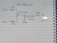
If not stacking the AD844 and using it as per Pedja Rojic circuit above, you may be able to null the TDA1541's rather large dc offset by using Abraxalito's nulling circuit (attached) but it gets messy with this and the 2SK170 Pedja Rodic's network all hooked up to the AD844's input, hate to seen what the noise ends up as.
Cheers George
Cheers George
Attachments
Last edited:
..... seeing your using the TDA1541A which has 3 to 4 times the output current (4.6mA) of my PCM1704k (1.2mA) I'm not surprised you prefer 3 stack 844 I/V, in fact I think it could need 4 stack, as Mick Meloney of Supratek found out with his TDA1541 setup!
Cheers George
Hi George,
Give AD811 a go. It will provide dynamic impedance of less than 1 ohm to vulnerable 1704 output of a milliamp (on a good day). It is an outstanding DAC, but it really requires close to zero impedance to work properly. Attached pdf's / jpg will be more than enough to give you some idea on what to pay attention to when using 811.
Nick
Attachments
Hi George,
Give AD811 a go. It will provide dynamic impedance of less than 1 ohm to vulnerable 1704 output of a milliamp (on a good day). It is an outstanding DAC, but it really requires close to zero impedance to work properly. Attached pdf's / jpg will be more than enough to give you some idea on what to pay attention to when using 811.
Nick
Hi Boky, like my little dig at Jocko over on DIYHIFI?
I've had an 811 here by a friend who used it as I/V and it's good but has the typical sound of a feedback type opamp as an I/V stage, still didn't come close to the sound of the AD844 which is far richer in body and sound stage, and able to do a disappearing act of the speakers yet staying tight, controlled and very dynamic, without ever getting hard.
I believe it's because of the absence of global feedback the way we can use it is the reason the AD844 sounds like this. As the very HF glitches and noise that come from dacs maybe upsetting to feedback type I/V opamps, and because the AD844 has no feedback the way we use it, those glitches and noise from dacs are far less upsetting to it.
As we know a poweramps with less global feedback, even less local feedback are much more stable for the same given bandwidth and gain than poweramps with more feedback. This I believe is the secrete to the AD844 with it's TZ point to control the gain with no feedback, no other opamps I know have this TZ point.
I've corresponded with Barry Gilbert the Analogue Devices designer of the AD844, and he was very chuffed to see what we've been doing with it here.
I asked him if there was any chance to see the complete full schematic of it instead of just the simplified one on the data sheet, he did say he would get it to me if he can find it, but I have not received it as yet.
Cheers George
......AD844 with it's TZ point to control gain..
Hi George ...I wonder if you could please teach me as a beginner how I can set the gain adjustment using the AD844 TZ with the AD844 buffer in stacked configuration? Ive read most of this thread and the AD844 datasheet but I wonder if you can dumb it down for me with you going onto stacking the AD844 buffer for a AD844 pure IV output!
Is the gain just set simply by a resistor value from TZ to ground ?
When your stacking for buffer out do you also solder all the TZ legs together and use just one resistor to ground? Or do you have the stacked TZ legs separate and use individual resistors on each of the AD844 TZ legs?
How do you work out what value resistor to select to get the desired output e.g I only need 1.2Vrms for my preamp sensitivity?
It seems from the datasheet the AD844 gain usually set using a resistor between Vout and -Vin in a feedback loop but youre using TZ to ground?
Is it still possible to null any DC out on the buffer output stage while dialling in the R1 value for the correct gain?
Cheers
Zap
Hi George ...I wonder if you could please teach me as a beginner how I can set the gain adjustment using the AD844 TZ with the AD844 buffer in stacked configuration? Ive read most of this thread and the AD844 datasheet but I wonder if you can dumb it down for me with you going onto stacking the AD844 buffer for a AD844 pure IV output!
Is the gain just set simply by a resistor value from TZ to ground ?Yes
When your stacking for buffer out do you also solder all the TZ legs together and use just one resistor to ground?Yes Or do you have the stacked TZ legs separate and use individual resistors on each of the AD844 TZ legs?
How do you work out what value resistor to select to get the desired output e.g I only need 1.2Vrms for my preamp sensitivity? For you use 1.5k, I want more so I use 2.7k
It seems from the datasheet the AD844 gain usually set using a resistor between Vout and -Vin in a feedback loop but youre using TZ to ground?We aren't using any feedback
Is it still possible to null any DC out on the buffer output stage while dialling in the R1 value for the correct gain?Nulling is done with 20kohm trimpot on pins 1 and 8 and positive on just one AD844 see page 14 of data sheet (the 20ohm trimpot is a typo should be 20kohm)
Cheers George
Cheers
Zap
Last edited:
I played with 844 and 1541. It never really grew on me (the 844), most likely due to the high distortions of a diamond non-feedback implementation; in particular the harmful IMD. The sound character you are describing is more due to the NOS DAC topology, then to 844 itself. 844 has quite cold and sterile presentation. Again, this is my conclusion from years of 1541 experience. 1541 with a I/V resistor, followed by tube gain stage, sounded much better to me - it was very very nice!
I was referring to 1704 - it simply has to be used with a stage of sufficient gain, and it has to see impedance close to zero at its output. Hence my suggestion. It's like having a very low value resistor I/V - only with a gain. There simply isn't anything better out there if you need to do I/V with 1704. I still think that you may find properly designed 811 stage to be exceptional... once you tried it for yourself.
Nick
Hi,
I wouldn't regard the AD844 as a typical diamond implementation, apart from the output buffer.
As the diamond is a cascade of two emitter followers its certainly a low distortion, 100% (degenerative) feedback structure.
Its just that the feedback is applied locally and not globally.
Why this should result in increased IMD is not obvious at all.
The I-V related part of the AD844 as used here, is nothing other than a current buffer, that -in opposite to the more common voltage buffer- features a very low input impedance and a very high output impedance.
Other than that it just mirrors the input signal current into the I-V resistor.
As such it offers the DAC-outputs a advantageous environment compared to a I-V resistor followed by a voltage gain stage.
The distortion of a DAC loaded by a non-null impedance load (I-V resistor) rises with rising value.
Besides the input stage of the voltage amplifier is a transconductance stage, which converts the just I-V converted signal voltage into a current again.
The current buffer leaves the signal in the current domain, hence one process less.
At the same the current buffer offers a I-V resistor improved conditions as its internal current mirrors are superior current sources than most any DACs outputs.
As such low distortion without the requirement of global feedback loops is quasi inherental to this circuit structure.
Built with discrete devices the supply line voltages and the value of the I-V resistor could be chosen so high that the output voltage becomes sufficient to drive speakers, by only adding a powerful enough voltage buffer.
That would be a so called Power-DAC.
So I kindly but fimly disagree with Nick about the quality of I-V conversion stages.
Its positive in technical respects -and imho including sound quality too- to keep the signal handling longer in the current domain.
@kazap
The I-V resistor is direct part of the signal path. The DACs signal current is precisely mirrored into that resistor.
The current flow generates the signal voltage drop over this resistor.
As resistor type I'd suggest a high quality, stable precision thin-film resistor, like Susumu's NiCr resistors (RG or similar) or Vishay's BMFs.
A Pot connected as variable resistor may be used to trim output voltages, or to create a generally variable output (volume control).
Keep in mind though that a pot won't have the low temp coefficient nor the channel balance of a fixed value resistor.
jauu
Calvin
Last edited:
If not stacking the AD844 and using it as per Pedja Rojic circuit above, you may be able to null the TDA1541's rather large dc offset by using Abraxalito's nulling circuit (attached) but it gets messy with this and the 2SK170 Pedja Rodic's network all hooked up to the AD844's input, hate to seen what the noise ends up as.
Cheers George
You mean we use the Abraxalito nulling circuit and the 2SK 170 circuit at the same time ?
What is the function of the VR 1 near to the 2sk 170 ?
thks
kp93300
I've never done it to the TDA1541, only to PCM1702 and PCM1704 you better off asking someone who has.
I know Mick Meloney of Supratek has with the TDA1541, but he also used a tube buffer after the 4 x stack of AD844 which is needed with that dac chip because of it's very high output current, but it has a large dc offset as well, but because he used a tube buffer with coupling cap, that may have addressed that problem.
Cheers George
Hi george,
I implemented the stacked AD844 type i/v about a year ago (i am using 3 chips stacked)and was very impressed with the result. My digital sources are a NOS AD1865 DAC and a Rotel RCD 991 player with its PMD1000 filter and PCM63 DAC. I was using the Rotel as a transport with the AD1865 DAC, passive i/v and on to my DIY Allen Wright FVP5A pre-amp. This gave me just enough gain and I slightly preffered the AD1865 DAC to using the Rotel's own filter/DAC with the same i/v and gain stage.
I put the AD844 i/v in the Rotel for simplicity and because it sounded so good I haven't felt the need to trial the AD844 with the AD1865 DAC.
Currently I am using the internal buffer on the AD844 taken from just one of the chips, again because it sounds good so I didn't feel like fiddling with external buffers. But I am interested in optimising this set-up so I was interested in the possibility of summing the outputs from all the stacked chips with 100R resistors.
Have you or Art/Dave actually tried this? Should I add this mod to my set-up or go straight to a seperate buffer?
Thanks for all the info in this thread, George !
Rod
- Home
- Source & Line
- Digital Line Level
- Using the AD844 as an I/V