After reading about the SE KT120 car audio amp kit here and the tube SMPS thread here, I thought I would reach out the the developer of the amplifier. I was curious to see if he was interested in developing a stand alone SMPS for tube amplifiers. It turns out that he has done some work on such a design but he plan on having it run off of 13.8V, for car use. He is also looking for some input as to the design itself. Would you guys like to add some input?
I will post our correspondence below.
I will post our correspondence below.
I have 2 questions. I was wondering if you will be releasing a stand alone SMPS for tube amps that runs off of 12V? There are few people on diyaudio that would be interested in one. I was also wondering if you will be making a 120V of the monobocks? Any chance it would be easy to modify the PCB to work of 120V?
I have a standalone power supply in the works. For the most part it’s the same one that I use in the monoblock. I’m having trouble making a few decisions or I would already be producing them. My dilemma is I’m fairly confident I can come up with a design that produces over 250w but I’m not sure if that much power is really necessary. I’m also on the fence about whether to include a heater voltage supply on the standalone unit. Start a thread and see what people want. If there’s enough interest I will make it. Send me back a link so I can follow along.
I don’t have a 120v solution yet but I’ve been using and suggesting this:
25A 14v DC Power Supply for Chargers (350W)
It runs 2 kt88 monoblocks nicely. It should run 2 kt150’s but I suggest using separate supply’s for that application. The monoblock draws about 8a with an el34 and about 12a with a kt150. The 120v question comes up a lot so I have been putting thought into a 24v version. This will reduce current significantly and make it easier to run on 120v. I’m thinking I can modify my existing design by changing the windings on my transformer to accomplish this. I also plan to make a 120v monoblock at some point. Finding time for all this is the biggest problem.
Would you mind if I used your response in the topic? I don't mind starting one and seeing what interest is out there. I do know that guys on the site are going to want to know more about the design than just the voltages and current abilities. Output impedance, switching frequency, noise, etc. are all things they are going to be interested in. Do you have some of that info available?
You can post my responses. Switching frequency is 60k/2, quesent current is 280ma, efficiency is 84% @50w – 87%@100w and 92%@150w. Output regulation is 4% under 100w. I don’t have a measurement for over 100w. noise is 2.5mvrms. When I designed the power supply I added output capacitance until there was no measurable ripple across my speaker load then used a small filter in the pre section but none is required in the power section. The monoblock I make is dead quite.
I find SMPS to be a little problematic in tube amps.
For B+ supply, there aren't too many HV regulators available. Even if you build a floating one (is this even possible with integrated smps regulator chips?), it still needs to cover the +/-10% line variation, which at 400V B+ quickly amounts to 80Vpp line regulation capability. Another possibility would be too boost from a lower voltage, but boost converters perform badly / noisy, and it's a pita to clean up the hf garbage in a post regulator.
B2+ reguation for pre-amps looks a little more friendly because of generally lower voltages and low currents. Maybe a discrete HV smps design with a clean up linear regulator behind will perform adequately. But then again, the power wasted in a low current linear B2+ regulator is not dramatic, so the main advantage of the smps doesn't even come into play...
SMPS for DC heaters can be a good choice. Heater voltages match with existing regulator ICs, and linear regulators are horribly inefficient at low voltages and high currents. It's easy to waste more power in a linear regulator than in the heaters... Also, heaters have no particular demands regarding regulator output impedance, which could be problematic with smps.
Have no idea where you get these figures from...
Been designing SMPS for 25 years for MIL applications up to 20kV ...
400V is not considered High Voltage for SMPS....
PP and Bridge converters can do this with ease with better than 1% Line-Load regulation... Can make them reasonably small if switching over 500kHz...
With rock solid stable control loops with better than 80 degrees of Phase Margin and fairly quick cross-over points...you will not experience any problematic situations ...
Last edited:
Okay then, I'm always willing to learn. Let's forget about categories like "high voltage" and such. Can you post a design for approx. 150V to 400V DC, ~0.2A load current? This would resemble some medium power tube amp load.
Do you agree that step up converters are noisy?
By 1% regulation you mean factor 0.01 or -40dB? Not quite hi-fi.
Do you agree that step up converters are noisy?
By 1% regulation you mean factor 0.01 or -40dB? Not quite hi-fi.
Some step up converters are noisier than others.... You are referring to "Boost" regulators.....it is NON-ISOLATED Converter, not the best choice for many reasons....basically an inductor, Duty Cycle limited for large conversion ratios unless it is tapped, then the waveforms get real ugly...
The Push-Pull as well as the Bridge converters have ISOLATED secondary windings that can be adjusted to allow a high conversion ratio while maintaining reasonable Duty Cycle around 40% to 50% ....
As for regulation.... traditional "Transformer - Rectifier" designs used in tube amps have ****-poor regulation... There for the tube amps are typically designed at voltages obtained when at full power output.... Many Class AB tube amp power supplies will dip 50V to 100V range from idle to full power output...
The closed loop SMPS can achieve much tighter voltage regulation over load...figure a volt or two at worst case..
Output ripple can be as small as a couple tenths to hundred milivolts at switching frequency..figure 500kHz....
Input current harmonics typically roll-off at ( 1/f ) starting at the switching frequency up to the rise time frequency then roll-off at ( 1/f^2 ) .....
Last edited:
Can you post a design for approx. 150V to 400V DC, ~0.2A load current? This would resemble some medium power tube amp load.
OK...
This is the 40 watt isolated flyback that I mentioned in the other thread. The PCB (3" x 6", meets applicable safety standards) is in fab now. We'll see how it works.
Flybacks can be noisier than push-pull or bridge converters (due to the higher peak currents, mostly), but they are simpler and are the "usual choice" for offline supplies under 100W.
That said, most of the worry about noise when using switchers in audio is pure superstition. 60Hz rectifiers inject a lot more junk than a properly designed SMPS.
When I was at TI I did some work to determine how much a typical DC/DC flyback would interact with an audio DAC and amplifiers. Even in the worst case (with the SMPS synched 1kHz away from the sample rate), any artifacts were at the limit of measurablility, like -95dB...
Class D amps are an entirely different matter. You can get some, uh, interesting interactions between the SMPS and the amp carrier.
Pete
Attachments
Last edited:
OK...
This is the 40 watt isolated flyback that I mentioned in the other thread. The PCB (3" x 6", meets applicable safety standards) is in fab now. We'll see how it works.
Flybacks can be noisier than push-pull or bridge converters (due to the higher peak currents, mostly), but they are simpler and are the "usual choice" for offline supplies under 100W.
That said, most of the worry about noise when using switchers in audio is pure superstition. 60Hz rectifiers inject a lot more junk than a properly designed SMPS.
When I was at TI I did some work to determine how much a typical DC/DC flyback would interact with an audio DAC and amplifiers. Even in the worst case (with the SMPS synched 1kHz away from the sample rate), any artifacts were at the limit of measurablility, like -95dB...
Class D amps are an entirely different matter. You can get some, uh, interesting interactions between the SMPS and the amp carrier.
Pete
Hi Pete...
You have a nice affordable SMPS .....looks good...
I may have met you years ago... I used to work at National Semiconductor and later International Rectifier, designing SMPS IC's .... Most of the team went to LT and some stayed on with TI .... Your name sounds familiar...
pete,
will you be selling these on e-bay eventually ?
Well, probably. Assuming it works as it should
")
Like I mentioned in the other thread, I am a little worried about electrical safety with DIYers...
Pete
Sorry for the temporary thread hijack...
As to the original post - it seems like a rational design to me, and I think it would be a useful thing to have available to DIYers.
There is some advantage to using a DC input voltage, so you can avoid line (mains) safety issues. 13.8V (automotive) or 24V would both be reasonable input voltages - 24V better for lower input current. And you can buy plenty of 24VDC output switchers for cheap to power the whole thing from the mains.
I would suggest adding a big buck regulator to power heaters. Maybe 6.3V at 5-8A out. Ideally, sync it to the B+ switcher, maybe at 2x the switching freq. Otherwise, any noise that does get through can intermodulate with any B+ noise and you can get artifacts down into the audio.
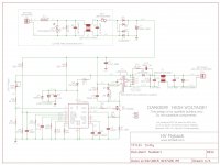
BTW, the original schematic is here: http://pjlelectronics.com/images/SE_MONO_BLOCK_power_supply.pdf
No association with the creator, BTW...
Pete
As to the original post - it seems like a rational design to me, and I think it would be a useful thing to have available to DIYers.
There is some advantage to using a DC input voltage, so you can avoid line (mains) safety issues. 13.8V (automotive) or 24V would both be reasonable input voltages - 24V better for lower input current. And you can buy plenty of 24VDC output switchers for cheap to power the whole thing from the mains.
I would suggest adding a big buck regulator to power heaters. Maybe 6.3V at 5-8A out. Ideally, sync it to the B+ switcher, maybe at 2x the switching freq. Otherwise, any noise that does get through can intermodulate with any B+ noise and you can get artifacts down into the audio.
BTW, the original schematic is here: http://pjlelectronics.com/images/SE_MONO_BLOCK_power_supply.pdf
No association with the creator, BTW...
Pete
Possibly relevant:

Enough power for a preamp, say. The basic design could be scaled up, or a proper controller chip used, or any other topology (a current mode push-pull would be quite reasonable), for running a whole power amp.
Besides controlling RF emissions, beware of the automotive environment: there is some noise to be expected, as well as dips (the equipment should continue to operate even at low voltages, corresponding to a heavy load on the electrical system, if not during starting), reversal (typically, accidental connection during wiring in a new battery, or jump-starting), overvoltage (e.g., jump-starting from a higher voltage chassis) and load dump (battery becoming disconnected while alternator is at balls-out full rev).
So you wouldn't want to run heaters directly on the raw mains, because the voltage is poorly controlled. A buck could be used, or another winding on the main (HV) output, as above. Either is fine. You do get the advantage that, if it's a secondary winding, you can apply DC bias to reduce heater-induced noise. Which shouldn't be a problem being rectified and filtered, but may still be a subtle benefit in low noise applications (gee, not like you'll be doing hi-fi listening to a record player inside a moving vehicle... ).
Tim
Enough power for a preamp, say. The basic design could be scaled up, or a proper controller chip used, or any other topology (a current mode push-pull would be quite reasonable), for running a whole power amp.
Besides controlling RF emissions, beware of the automotive environment: there is some noise to be expected, as well as dips (the equipment should continue to operate even at low voltages, corresponding to a heavy load on the electrical system, if not during starting), reversal (typically, accidental connection during wiring in a new battery, or jump-starting), overvoltage (e.g., jump-starting from a higher voltage chassis) and load dump (battery becoming disconnected while alternator is at balls-out full rev).
So you wouldn't want to run heaters directly on the raw mains, because the voltage is poorly controlled. A buck could be used, or another winding on the main (HV) output, as above. Either is fine. You do get the advantage that, if it's a secondary winding, you can apply DC bias to reduce heater-induced noise. Which shouldn't be a problem being rectified and filtered, but may still be a subtle benefit in low noise applications (gee, not like you'll be doing hi-fi listening to a record player inside a moving vehicle...
).Tim
Some of the bigger offline SMPS (300+ Watt say) have a ferrite Xfmr that can be accessed to replace the existing secondary with a parallel bunch of thinner windings (say a 48V winding, with a Litz wire rewind). One new winding fills the existing output/regulation function, and the other windings get individual full wave rectifiers. These all get the DC sides summed to obtain the high voltage B+. The individual secondary wires on the xfmr just have DC between them, so no added HF capacitance occurs for the driving circuitry. The Litz will need good insulation on the strands to withstand the HV DC.
Some price range suggestions would also help.
I spent some time experimenting with a 6.3v winding on my existing product. HV regulation made it difficult to implement. A big buck would be my preference and “sync it to the B+ switcher” is a very interesting suggestion. If implemented correctly it could provide benefit and reduce costs.
All of this has been implemented at one level or another: “Besides controlling RF emissions, beware of the automotive environment: there is some noise to be expected, as well as dips (the equipment should continue to operate even at low voltages, corresponding to a heavy load on the electrical system, if not during starting), reversal (typically, accidental connection during wiring in a new battery, or jump-starting), overvoltage (e.g., jump-starting from a higher voltage chassis) and load dump (battery becoming disconnected while alternator is at balls-out full rev)”
I’m open to criticism and I want to hear about it if a particular aspect of my product needs improvement. Be specific. You won’t hurt my feelings.
I like the idea of laptop psu and think it’s worth spending time on. I personally have a small collection of them and I’m assuming most people here do as well. For now let’s say we need something in the 10a range. Are they available new at a reasonable price?
Most laptop supplies are around 19V and 2-3A. I am not sure I have seen a 10A laptop power supply.
As for a price range it is hard to come up with a number. I bought one of these from Siliconray but I have not used it due to it's lowish output voltage. I don't remember offhand how much he was selling them for.
As for a price range it is hard to come up with a number. I bought one of these from Siliconray but I have not used it due to it's lowish output voltage. I don't remember offhand how much he was selling them for.
Most of the team went to LT and some stayed on with TI ....
Speaking of LT -- they have several controllers and gate drivers which allow the switch to operate in the linear portion of the curve in a "controlled slew rate" fashion -- albeit with a penalty to efficiency. You can do this with discrete components too, but I believe that the LTC solution is neat. No DIP packages, either SOIC or TSSOP. I have some samples of LT3439 and LT1533 etc.
- Home
- Amplifiers
- Tubes / Valves
- SMPS Tube kit - Interested?