More results
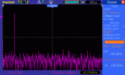
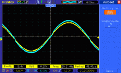
50000Hz:

You can see how harmonic distortion appears at this frequency.
In conclusion up to 30000Hz this amp delivers 216Wrms at a very good fidelity.
I tested just the upper half of the bridged amp, speaker connected to GND and the 680ohm resistor connected to GND by a 22uF/50V capacitor.
The peak current through load is 19.2 x 1.41 / 1.7 = 15.97Amps.
The bridged configuration theoretically should delver 216 x 4 = 864W / 1.7ohm but the current will double to about 30Amps which is almost the limit of the power transistors. But on 4ohm load (19,2 + 19,2)**2 / 4 = 368Wrms on a peak current of 13.53Amps which is very acceptable.
50000Hz:
You can see how harmonic distortion appears at this frequency.
In conclusion up to 30000Hz this amp delivers 216Wrms at a very good fidelity.
I tested just the upper half of the bridged amp, speaker connected to GND and the 680ohm resistor connected to GND by a 22uF/50V capacitor.
The peak current through load is 19.2 x 1.41 / 1.7 = 15.97Amps.
The bridged configuration theoretically should delver 216 x 4 = 864W / 1.7ohm but the current will double to about 30Amps which is almost the limit of the power transistors. But on 4ohm load (19,2 + 19,2)**2 / 4 = 368Wrms on a peak current of 13.53Amps which is very acceptable.


Well done!
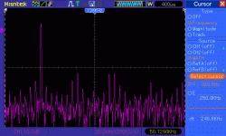
Nevertheless you can even in the 20 kHz see some small tops in the frequency analyser (not in the sinus wave). This implies a distortion of more than 1% I guess. Pity, you let not see it at 1 kHz. I expect it will be far less and even completely invisible at that frequency.
Could you measure again with f = 1 kHz and than remeasure Rsync = 1 or 0,5 Ohm with f = 1, 20 and 40 kHz? I am very interested in the results.
Finally this thread comes to an end with hard measurements. Congratulations cmorariu, well done!!!!!! You earn a MSc!
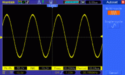
Thank you! Trust me, the 20KHz is as clean as 1KHz, the small tops are present even in the absence of the signal due to FFT computation algorithm of this tool. I increased the input signal at 20000Hz to push the amp into clipping and the tops at harmonics are very clear visible and stable, bigger at odd harmonics. I also scoped the slope of the pin 14 of the TDA and measured its incline at different frequencyes. Incine still increases above 20000Hz till about 35000Hz when reaches the slew rate and remain steady (at crossover). Increasing more and more the frequency the slope becomes triangular at the top also.
I did more tests.
- First I tested the TIP35/36C - the clipping starts at lower voltages, due to bigger Ube at high current. Instead of 19.2 Volts undistorted I got only 17.4V which is a significant loss of power (178W instead of 216W).
But the worse with this transistors is the Hfe which goes so low that they require more current from TDA and the chip tend to warm too much. Also due to smaller case and smaller heat transfer metal on the back (than 2sc5000) TIPs are running warmer also.
- Second I tryed one pair of MJ15003/MJ15004 (TO3 case, Pd=250W, Ic=20A) figuring out that a pair should be sufficient. They behave very similar to TIP35/36C, clipping at lower voltages and warming too much.
- Third I started with 6.8 sync resistor and monitored using a laser thermometer the temperature of TDA (I use for tests a very big radiator, and a cooling fan to blow air under it, to simulate an ideal rad). I decreased gradually the value till 5.1ohm monitoring the temp. At 5.1ohm (1KHz and full power) the temperature of TDA reaches 50oC.
I don't want to push it harder because I intend to build a long lasting amplifier using regular radiators. At this value I got a good compromise between dissipation and fidelity.
OK.
In the photo I see you still use 0,1 Ohm in the emitters. Why do not you skip them? With 16A they alone loose 1,6V! That is very much! They increase temperature of the TDA a little bit and decrease severely the clipping voltage. I.m.o. they are not necessary for security if you only use one pair of end transistors.
In the photo I see you still use 0,1 Ohm in the emitters. Why do not you skip them? With 16A they alone loose 1,6V! That is very much! They increase temperature of the TDA a little bit and decrease severely the clipping voltage. I.m.o. they are not necessary for security if you only use one pair of end transistors.
If only one transistor per polarity is used they can be skipped unless you want to implement a current limitation circuit (as I intend to do). But when more than one transistor per polarity are connected the 0.1ohm resistors are necessary and very important to balance the currents through this transistors, since in the real word no Ube twins are possible.

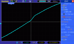
Out and transistor base signal
@zanden30 - I'm sure you will like this! I scoped the signal at pin 14 of TDA (down) and the output of amp at 20000Hz at a lower output level where small modifications of slope are more visible. You can see the "jump" of the base signal and the behavior of the output. This may explain a lot
@zanden30 - I'm sure you will like this! I scoped the signal at pin 14 of TDA (down) and the output of amp at 20000Hz at a lower output level where small modifications of slope are more visible. You can see the "jump" of the base signal and the behavior of the output. This may explain a lot
Attachments
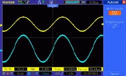
Base and output overlapped
This picture is more relevant I think. The jump comes over 0.6V till about 2.6V, the reason is most probably what I wrote before. But the picture reveals another interesting thing, compare the crossover portion with the "jump". At 20000Hz is plenty of slew rate reserve at crossover, the jump portion is done in the quickest way to correct the step in of transistors, thus that is done at a greater slew rate. I zoomed on the scope, the jump is of about 2V in 1uS, i.e. one fifth of the max slew rate That confirms that the circuit has full capability to correct its output by the feedback loop even at this frequency.
This picture is more relevant I think. The jump comes over 0.6V till about 2.6V, the reason is most probably what I wrote before. But the picture reveals another interesting thing, compare the crossover portion with the "jump". At 20000Hz is plenty of slew rate reserve at crossover, the jump portion is done in the quickest way to correct the step in of transistors, thus that is done at a greater slew rate. I zoomed on the scope, the jump is of about 2V in 1uS, i.e. one fifth of the max slew rate That confirms that the circuit has full capability to correct its output by the feedback loop even at this frequency.
Attachments
Some math related to this amp
First about Nyquist-Shannon theorem invoqued by Zanon30. This is all about digital signal processing. Is required that the digital SAMPLING RATE to be at least twice of the max frequency of the analog signal in order to be able to decently reproduce the analog signal from digital. Is not at all our case, we are working here with pure analog signals.
As you know the equation of the sine wave is A*sin*(2*PI*f*t). The incline of the slope is given by its derivative, i.e. A*2*PI*f*cos(2*PI*f*t).
Is obvious knowing the evolution of cos(x) function that the greatest incline is at crossovers when the argument becomes =0 and cos(x) = 1. Thus the most demanding in terms of amp slew rate is the crossover.
Now let's see in my case what is the required incline at crossover for 20000Hz. It is 27V * 2 * 3.14 * 20000 * 1 = 3.39 V/uS.
As stated by datasheet (and my measurements) the typical slew rate of TDA7293 is 10V/uS which is three times greater, more than enough to reproduce with fidelity 20000Hz at 27V amplitude (54Vpp). Thinking at Zanden30's triangle equation, the conclusion is that SYNC resistor must be no more than double the impedance of load to keep the pin 14 of TDA below datasheet slew rate requirement. In my case it is 5.1 ohm (instead of 1.7 * 2 = 3.4ohm). What explains the lack of distortion up to 30000Hz? Maybe slew rate is greater at low loads, maybe the input capacitance of transistors that bootstrap the sync resistor? Anyway if you trust more the math than practice, at this popular transformer voltage of 2x24Vca keep SYNC resistor at no more than double of the load impedance!
For those willing to drive extremely low impedance loads, use lower voltages to reduce slew rate requirement.
I agree with your math.
Remark could be made that only 20 kHz sinus can be processed in your calculation, and no other signal with (unaudible) harmonics. Nyquist indeed aplies to sampling.
It is amazing that this easy scheme delivers such good performance. Dr Frost really had a brilliant idea!
Remark could be made that only 20 kHz sinus can be processed in your calculation, and no other signal with (unaudible) harmonics. Nyquist indeed aplies to sampling.
It is amazing that this easy scheme delivers such good performance. Dr Frost really had a brilliant idea!
Some remarks about unaudible (ultrasonic) harmonics
First let's consider 20000Hz the upper limit of audible frequencies. This is a convention because each of us has a different audible acuity, usually the upper heard frequency by different humans is much lower, about 12000-16000Hz.
Second, remember that Fourier demonstrated that any repetitive signal of any shape can be decomposed in a sum of sinusoids, each having a different amplitude and frequency.
Third, an audible signal of any shape decomposed, is a sum of audible frequency sinusoids.
Forth, remember that the goal of an high fidelity amplifier is to amplify(magnify) the input audio signal, without distortions (modifications of signal shape).
Now consider that a pure sinusoid of 1000Hz is applied at the amp input. We expect to have a 1000Hz pure sinusoid of bigger amplitude at the output. But what happen when the volume is increased over the limit of clipping? The output signal will be a flat top and bottom sinusoid which is a different shape signal than the input. This altered signal is not a pure sinusoid so it will be a sum of sinusoids. Practically it means that beside the 1000Hz sinusoid some other sinusoids will appear at the output. Most of them are at frequencies multiple of basic frequency (1000Hz) (harmonics). We can split this additional sinusoids on a frequency basis in two categories, sinusoids having the frequency below 20000Hz(audible limit) and sinusoids having the frequency above 20000Hz (ultrasonic).
The audible harmonics will be reproduced by speakers along with the basic signal, damaging the sound (causing sound distortion). The ultrasonic harmonics will put an additional load on amplifier and speakers, dramatically reducing efficiency.
Both, audible and ultrasound harmonics are undesirable so in a HIFI amp is necessary to avoid them.
I tested "Dr.Frost" amp, feeding it with "pure" sinusoidal signal from a HP professional generator to make sure that at all audible frequencies sinusoids are reproduced without distortions (modifications). That certify that the amp itself doesn't generate harmonics (audible and ultrasounds) and will reproduce with fidelity the shape of any audible signal.
After this test is sure that keeping the output power below clipping no additional sinusoids will appear, including ultrasonic harmonics.
But in the real world, the input signal is generated by less "clean" sources, as MP3 decoders/players, radio, CD players, computers etc. The output signal of this devices (except professional ones) most probably contain ultrasonic sinusoids, due to audio signal distortions or to digital to analogue conversion.
Connecting an MP3 player to an amplifier I noticed that the power transistors of the amp were warm even at low volume passages of sound. I scoped the MP3 player output signal and I found out that the 128KHz sampling frequency was present at the output along with the sound wave. I inserted a two pole Butterworth low pass filter between MP3 player and amp and solved the warming problem.
CONCLUSION: to avoid audible and ultrasonic unwanted harmonics:
1. Be sure that the amp itself doesn't generate them, by:
a) testing the fidelity of the amp at all audible frequencies
b) adding a clip detector and keeping the output power of the amp below clipping
2. Filter off ultrasound harmonics at the output of the source of sound signal by using a sharp low pass filter
Dr. Frost Amplifier, enhanced fidelity
Many built this amp proposed by Dr. Frost and were delighted by it's quality and easiness to build. The sound is great for such a simple circuit but as discussed in previous posts it has its pitfalls. As zanden30 mathematically predicted some distortion exists at crossover at high signal and high frequency, fixing it overheats the chip and is a matter of fine tuning to achieve that. Also, as I experimentally discovered a glitch is present at the moment of power transistors "step in" and I published a very clear oscillogram showing it. Of course all this exists in an acceptable low level of distortion and the circuit still remains a very great idea.
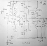
Being a perfectionist I wanted to fix all this pitfalls still sticking to Dr.Frost circuit and trying to keep the amp as simple as possible.
If you look at the attached schematic, the additional components are 2 transistors (TIP41C & TIP42C), 4 resistors (2 x 2.4K/5W and 2 x 0.75/5W), 2 diodes 1N4007 and 1 capacitor of 0.1uF.
They form a medium power class AB stage who's essential goal is to drive the load around crossover and at low output power. This stage contribute to total power even at high signal but it's contribution is "shadowed" and limited by the step in of power transistors. I dimensioned the emitter resistors of TIP transistors to limit the peak current at about 2 - 2.5Amps. The negative feedback loop of current realized on 0.1ohm emitter resistor improves the linearity of output at power transistor step in.
On 4ohm, at +/- 40V this amp delivers 170W at practically no distortion!
Bridging two, 340W can be delivered on 8ohm. (If you want 680W on 4 ohm add one more pair of 2SC5200/2SA1943 for each amp)
Many built this amp proposed by Dr. Frost and were delighted by it's quality and easiness to build. The sound is great for such a simple circuit but as discussed in previous posts it has its pitfalls. As zanden30 mathematically predicted some distortion exists at crossover at high signal and high frequency, fixing it overheats the chip and is a matter of fine tuning to achieve that. Also, as I experimentally discovered a glitch is present at the moment of power transistors "step in" and I published a very clear oscillogram showing it. Of course all this exists in an acceptable low level of distortion and the circuit still remains a very great idea.
Being a perfectionist I wanted to fix all this pitfalls still sticking to Dr.Frost circuit and trying to keep the amp as simple as possible.
If you look at the attached schematic, the additional components are 2 transistors (TIP41C & TIP42C), 4 resistors (2 x 2.4K/5W and 2 x 0.75/5W), 2 diodes 1N4007 and 1 capacitor of 0.1uF.
They form a medium power class AB stage who's essential goal is to drive the load around crossover and at low output power. This stage contribute to total power even at high signal but it's contribution is "shadowed" and limited by the step in of power transistors. I dimensioned the emitter resistors of TIP transistors to limit the peak current at about 2 - 2.5Amps. The negative feedback loop of current realized on 0.1ohm emitter resistor improves the linearity of output at power transistor step in.
On 4ohm, at +/- 40V this amp delivers 170W at practically no distortion!
Bridging two, 340W can be delivered on 8ohm. (If you want 680W on 4 ohm add one more pair of 2SC5200/2SA1943 for each amp)
Attachments
- Home
- Amplifiers
- Chip Amps
- TDA7294 + Power Transistors AMP (TDA7293 to come also)