Hi Joel,
Most importantly, your schematic and component choices appear to be good.
Dual Bobbin (= split-bobbin) EI type transformers like the Hammonds are the correct type to use, and you can be confident that the problem is not with them.
It's fairly sure to be a layout problem. Yes, you do need a chassis, for best performance.
With the wiring of both filament and HV supply, try to keep the wires between trafo - rectifier - caps very short. Allowing these to snake about increases the danger of coupling. 6"/150mm is a short distance in coupling terms, when the voltage swings at the rectifier are in 845 dimensions.
Please do not remove the 10uF cap in your CLC filament raw dc. This controls transient voltages at the choke input.
Since you found that the hum reduces when you put a hand near the rectifier, it could be coupling from the PS to the grid wire. If you have a metre or so of properly-rated HV cable, you could move the trafo/rectifier/caps away from the 845 to see if the buzz subsides. Keep the last HV cap near the 845 though, or it may become unstable (this could even be the problem!).
If you are still stuck, post some photos of the layout, preferably labelled for power & ground wires. And - how sensitive are your speakers?
Since insufficient information on how the spectrum graphs were produced, it means nothing. Anybody can post any sort of graph which may reflect unkown errors in measurement technique.For examples, there's no need to take my word for it: Take Bela's 300B FFT-comparison of dc & ac:
http://www.diyaudio.com/forums/tube...-300b-set-satoru-kobayashi-3.html#post4030013
The sidebands around the signal in the ac-heated case are gross (even at 1W output, the first spur is only 50dB down).
However, a DHY with its heater energised by balanced AC can be modelled by considering it as several small tubes with their grids and anodes paralleled. Intermodulation between heater AC and the grid signal will occur right enough, however:-
1) If the filament supply is balanced so that the filament AC (no signal present) is not heard in the output, that means the conribution of the small equivalent triodes at one end of the filament are balanced out by the equiv triodes at the other end. If this is so, then when signal is present, the intermod spectra generated on one side are opposite in phase to the other side and thus mutually cancell out within the tube.
2) If any hum in the output is low enough to be unobtrusive, then any intermod betwen that hum and the signal (which is the mathematical product of the two) must be even lower. This is just high school trig math. So if you can;t hear the hum, you can't possibly hear the hum intermod.
These reason are based on logic and are self evident.
3) There is also a third reason, well understood by those who study how the ear actually works. Because the inner ear is essentially a set of low Q narrow band filters covering the whole audio range in constant ratio progression, there is the phenomena of "masking". If a tone is very close to another higher level tone, and the level of theh lower tone is two low to cause audible beats (ie nore than 30 to 40 dB down), then the close-in lower amplitude tone is inaudible. If you have a tone at 100 Hx, and there's another at 150 Hz at quite a bit lower in level, the 150 Hz will be audible as a change in tonal character. It will be audible because the the two tones will excite different hair cells in the cochlear. But if it's 2000 Hz and 2050 Hz, the 2050 Hz tone will be a lot less audible and may well be inaudible (ie no tonal character change), as the same hair cells are excited by both tones. This does depend somewhat on the individual.
Well, yes, it will be if the tube gm is the same but the filament AC voltage is doubled. But twice stuff all is still stuff all.With the 10V filament of the 845, the effect is even worse than the 5V 300B.
Well, I;ve worked on high powered AM broadcast transmitters. They used enormous directly heated power triodes and AC heating. There was never a trace of hum audible on proffesional off-air monitors, and not a trace of hum intermod either. Inaudible and unmeasurable.There is no difficulty in hearing such degradation.
Once you put in rectification, you are virtually compelled to use a regulator. Not becasue of any effect on sound, but because the process of rectification worsens the effect on tube life from AC mains variation. But straight AC is fine if you do it right.Some folk think DC heating supplies sound worse, but that is only because they are comparing raw rectified dc or voltage regulators. The raw supplies couple in the recharge and recovery pulses in from the rectifier, and these really do sound worse than ac-heating.
Only an idiot would feed a filament with raw unfiltered rectified AC, as it will result in gross harmonic-rich hum that can't be nulled out.
You make no sense at all.The problem with voltage regulators (as opposed to current regulators) is more subtle. The filament has a differential signal voltage across it, due to the gm and bias skew brought on by the filament voltage gradient.
Take the 845 as an example. It draws 3.25 A at 10V. That means the hot resistance of the filament is 3 ohms. The signal cathode current, about 60 mA or so peak, then causes a potential across the filament of 180 mV, if the filament is fed from a true CCS. The signal grid voltage is of the order of 150 volt pk. So any distortion caused by the filament is greater than 58 dB down. That's absolutetle insignificant compared with the distortion generated from grid characteristic curvature. Actually, its a lot less than 180 mV, as not all the anode current is emitted from one end of the filament - its distributed along it.
If the filament is energised from a constant voltage source, that simply means that for signal frequencies the filament is shunted by a low resistance. So the signal frequency voltage on the filament is even less that the 180 mV max calculated above. So the distortion is even less than totally insignificant, even if the CV supply's impedance is somewhat indeterminate and non-linear.
This is all common sense.
Well it either succeeds in nulling or it doesn't. If it doesn't, the distortion is insignificant comapered to grid curvature. If it does, even if only partially, then the distortion must be even less. It cannot be greater.A voltage regulator - whose feedback is sourced directly across the filament - sees this music signal, and tries to null it out - clumsily, because it's an Ampere-level regulator.
You comment about clumsy ampere regulators is utter nonsense. A high current regaultor just has, by definition, a lower impedance than a low current regulator.
Last edited:
A typical Keit response.
You have no measured data to respond with, so we get a torrent of words instead.
It's really very simple. If you don't accept Bela's data, or mine, then please measure the IMD yourself, and supply the conditions and qualifications that will satisfy your own criteria. If you do this honestly, you will find that it is more or less as I have stated.
But this is just padding the thread out with irrelevances that do not merit addressing - unless anyone else thinks there is something worth answering, anyway.
Attachments

Last edited:
Anybody can post any sort of graph
Agreed. I can post multiple graphs of IMD produced as a result of balanced AC heating. Ain't pretty.
Can you? A whole lot of claims you made with zero proof.
Hi,
In your first thread you explained the way you have the ground as " The CT of the power transformer is connected to the ground of the first filter cap, this first cap is then connected to the ground of the second cap, and then the second cap ground is connected to the ground of the third cap, my ground connections for the power tubes are then connected to the ground directly at this third cap."
I ran into a problem one time fixing a Dynaco PAT 4 that I connected the PS ground at one side of the chassis and the capacitor in the middle of the chassis. That developed a Faint buzz like your experiencing. After few days decided to connected both ground at the same point and the hum when out. As you explained above I recommend/advice you to connect all caps individually to a common ground point . Them connect the PS ground and the tubes ground to this point. That will make star ground. It may solve or may not fix your problem like it fixed my problem. Just a try.
Okay, here are a few screenshots of my power amp as it stands.
There is no driver with this power amp.
I've built the driver in a separate chassis as it uses it's own power supply, and I'm only dealing with the power section that I've shown in the schematic earlier in the thread. So the driver has no bearing at all on the current buzz issue that I'm trying to work out.
I'm putting links to the pics as I don't want to shrink them in size at all.
http://i.imgur.com/OQay4um.jpg
http://i.imgur.com/GzKOg27.jpg
http://i.imgur.com/jhK0Dgx.jpg
Also, here's an audio clip of the buzz. I recorded with my phone, which is within millimeters of the tweeter to capture the sound.. The sound is subtle enough that about a foot back it's hard to hear.
https://soundcloud.com/thehoj-1/buzz-2
Agreed. I can post multiple graphs of IMD produced as a result of balanced AC heating. Ain't pretty.
Can you? A whole lot of claims you made with zero proof.
Yes, I can post graphs produced with errors in technique too. Or I can use carefull technique - trouble is, there is nothing to show.
You say zero proof, but I gave a logical explanation that is self evident - the only thing that is of solid value in an internet forum.
This is like arguing about whether area of a rectangle can be calculated by the product length and width. It's like saying you can't calculate, you need to measure the area. You don't need to measure to realise the truth of L x W.
To pick one example, I refuted Rod's claim that a constant voltage filamment source causes audible distortion. I explained that any signal voltage developed across the filament is so low as any distortion therrby caused is entirely negligible. I explained that the signal current (~60mA) by Ohm's Law can only develop within the filament resistance (3 ohm) LESS THAN 180 mV.
Now, you either believe Ohms' Law or you don't. I hope you do, because Ohm's Law is fundamental to electronics and has been in constant use for well over 100 years.
Rod claimed that intermod products of signal and filament AC energisation are audible. If the hum itself is inaudible, that cannot be - I explained the basis of that - it is the product of two sines - a trig identitity you learned in high school. Asin x Bsin y = ABcos(x - y)/2 + ABcos(x +y)/2. So if either of the two inputs is very small, the intermod outputs must both be small. You either believe high school trig or you don't.
Part of my argument is based on the fact that the human ear cochlear is essentially a set of narrow band filters in geometric frequency progression. So if two frequencies are close together they excite the same "filter" and so cannot be distinguished (unless they are close in level - you then hear the beats). You either believe that or you don't. You don't need me to prove it, because it is a well known medical fact. Look it up in any good text on ear anatomy and hearing.
Nice try, you make statements with no support.
Here is some proof. When you are ready to cease with the hand waving and provide some real data other than your religious beliefs, I will listen. Until then you are on ignore.
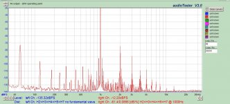
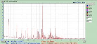
This is called IMD
Here is some proof. When you are ready to cease with the hand waving and provide some real data other than your religious beliefs, I will listen. Until then you are on ignore.
This is called IMD
Attachments
Also, here's an audio clip of the buzz. I recorded with my phone, which is within millimeters of the tweeter to capture the sound.. The sound is subtle enough that about a foot back it's hard to hear.
Soemting's wrong somewhere. You say you had to hold the phone close to the tweeter - so the buzz must have most of its energy in higher frequencies.
Earlier you said 10 uF across the transformer output made no noticeable difference - this indicates the buzz is mostly low frequency energy.
I guess your speaker cross over is at quite a low frequency.
It appears from your pics that the grid resistors are at the front just behind the cathode bypass caps. The earthing of the cathode bypass and grid bias must be long and tortuous but this isn't your problem. Try installing the grid resistors in a small metals box, with the connection to the grid as short as possible. Earth the box to the cathode bypass -ve connection point as directly as possible.
Are you certain the noise stops if you directly earth the grids (ie sort the grid resistors)?
The comment from Tauro about correct grounding of filter caps and single point earthing is normally good advice - prevents circulating hum currents. However, if shorting the grid resistors stops the noise then this is not likely to be your problem. Note that I said "not likely" - I didn't say "impossible".
Nice try, you make statements with no support.
Here is some proof. When you are ready to cease with the hand waving and provide some real data other than your religious beliefs, I will listen. Until then you are on ignore.
This is called IMD
Not proof at all.
Firstly, how were these graphs produced? You don't say. So they mean nothing. They could have been produced by mixing 60 Hz with 1 kHz in the input of an SS amp for all we know.
However, take the first one at face value. It shows straight 60 HZ hum only ~40 dB down. That's clearly audible in itself. Remember what I said. I didn't say intermod could never be heard. I said if the hum itself is inaudible, the intermod resulting from it will also be inaudible. And your graphs confirm that the intermod products are indeed at lower level - they are another 40 dB down from the raw hum. Inaudible.
Your second graph evidently was taken under different condtions but shows the same thing - the intermod products are lower in level that the straight hum.
As I said, when feeding DHT's with AC heating, you balance it so the hum is inaudible. One normally uses a trim pot to get really good balance.
And what about masking? You haven't refuted that.
Last edited:
Soemting's wrong somewhere. You say you had to hold the phone close to the tweeter - so the buzz must have most of its energy in higher frequencies.
Earlier you said 10 uF across the transformer output made no noticeable difference - this indicates the buzz is mostly low frequency energy.
I guess your speaker cross over is at quite a low frequency.
It appears from your pics that the grid resistors are at the front just behind the cathode bypass caps. The earthing of the cathode bypass and grid bias must be long and tortuous but this isn't your problem. Try installing the grid resistors in a small metals box, with the connection to the grid as short as possible. Earth the box to the cathode bypass -ve connection point as directly as possible.
Are you certain the noise stops if you directly earth the grids (ie sort the grid resistors)?
The comment from Tauro about correct grounding of filter caps and single point earthing is normally good advice - prevents circulating hum currents. However, if shorting the grid resistors stops the noise then this is not likely to be your problem. Note that I said "not likely" - I didn't say "impossible".
The speakers I'm using for testing are just cheap Technics 3-way speakers.. No idea what the specs are.
I did another recording which starts out with a 10uF cap clipped across the secondary of the output transformer.. At about 9 seconds I unclip it, and you actually can hear a small increase in buzz level with the 10uF cap disconnected.
https://soundcloud.com/thehoj-1/buzz3
Also if I put my ear nearly touching the midrange driver I can just barely hear a tiny bit of buzz as well, it's such a low level though, that when I move my phone in front of the midrange (about 15 seconds into the clip) I don't think it's perceptable.
I'll try to find some small metal boxes to encase the grid resistors in.
A 3-way system should have its tweeter crossover up fairly high - 3 kHz or more. That is the idea of 3-way systems. Crossover within the critical 300 Hz to 3 kHz band is undesirable. The woofer should not be called upon to reproduce any higher bass than necessary, or significant doppler intermod distortion will result. In 2-way systems these two requirements conflict.
10 uf will impose a cutoff around 3 kHz in an SE triode amp with no feedback.
Another thing you could try (I asume you do not have access to an oscilloscope):-
This tests the possibility of the tubes oscillating due to the long leads on the anodes. If you have a transistor radio with AM and SW bands, hold it near the tubes and see if you can tune into the buzz on the radio. If you can there's oscillation. Turn the amp off - If the buzz in the radio stops then it's the tubes are oscillating ie not something else in the house.
If this is your problem, the cure is usually easy. A 1 watt carbon resistor, 220 ohm or so, with as many turns of 0.5 mm wire wrapped round it as will fit is a typical cure. It must be installed in series with the anode, right at the tube socket.
I don't actually think this is your problem, for several reasons (845's aren't prone to it unless the wiring layout is really bad, usually the noise character will be different in each channel, the buzz arises because the oscillation is keyed to power supply ripple - you have plenty of filtering, and more). But it's easy enough to try.
Last edited:
A 3-way system should have its tweeter crossover up fairly high - 3 kHz or more. That is the idea of 3-way systems. Crossover within the critical 300 Hz to 3 kHz band is undesirable. The woofer should not be called upon to reproduce any higher bass than necessary, or significant doppler intermod distortion will result. In 2-way systems these two requirements conflict.
10 uf will impose a cutoff around 3 kHz in an SE triode amp with no feedback.
Another thing you could try (I asume you do not have access to an oscilloscope):-
This tests the possibility of the tubes oscillating due to the long leads on the anodes. If you have a transistor radio with AM and SW bands, hold it near the tubes and see if you can tune into the buzz on the radio. If you can there's oscillation. Turn the amp off - If the buzz in the radio stops then it's the tubes are oscillating ie not something else in the house.
If this is your problem, the cure is usually easy. A 1 watt carbon resistor, 220 ohm or so, with as many turns of 0.5 mm wire wrapped round it as will fit is a typical cure. It must be installed in series with the anode, right at the tube socket.
I don't actually think this is your problem, for several reasons (845's aren't prone to it unless the wiring layout is really bad, usually the noise character will be different in each channel, the buzz arises because the oscillation is keyed to power supply ripple - you have plenty of filtering, and more). But it's easy enough to try.
There are actually some labels on the back of the speakers. They're Technics SB-L42A, it lists some specs as well.
92db 1w/1m
Crossover:
3000Hz
6000Hz
I assume this means the tweeter is actually 6000Hz and up?.. That doesn't really jive.. I actually tried clipping a 100uF cap over the secondary of the output transformer though, and the sound pretty much disappeared.. I think I heard maybe the tiniest hint of a buzz from the tweeter, but it could have been my imagination it was so faint.
I also found these little metal boxes in my basement.. No idea I had them, so I was able to try encasing the grid leak and grid stopper resistors inside that, and ground the case to the -ve of the cathode resistor.. Didn't help
 .. I was so hopeful for that idea..

My anode leads are quite long though, probably 18" or so.. I'll try the idea of the carbon resistor with wire wrapped on it.. Although I'm not sure I have any carbon resistors in that value.. Metal oxide won't do the same thing?
Also, I do have an oscilloscope, but I can never seem to get the thing to cooperate.. It's a Philips PM 3234 dual trace.
Last edited:
There are actually some labels on the back of the speakers. They're Technics SB-L42A, it lists some specs as well.
92db 1w/1m
Crossover:
3000Hz
6000Hz
I assume this means the tweeter is actually 6000Hz and up?.. That doesn't really jive..
What it means is that essentailly you have a two-way system, a woofer and a tweeter croosing over at 3000 Hz, where it should do. And, a super-tweeter added to it, adding it's bit above 6 kHz.
Unfortunately that doesn't prove much you don't already know.I actually tried clipping a 100uF cap over the secondary of the output transformer though, and the sound pretty much disappeared.. I think I heard maybe the tiniest hint of a buzz from the tweeter, but it could have been my imagination it was so faint.
Metal oxide will work just fine, but may not be as reliable. The trouble is, the number of turns and resistor size may need to be customised to suit yourt amplifier. And when you reconfigure it for a neat layout in a metal chassis, the resistor with wire on it may need to be re-customised to suit the new layout.My anode leads are quite long though, probably 18" or so.. I'll try the idea of the carbon resistor with wire wrapped on it.. Although I'm not sure I have any carbon resistors in that value.. Metal oxide won't do the same thing?
Ahh! Great!. Is it not cooperating because you lack experince with oscilloscopes, or because it's faulty?Also, I do have an oscilloscope, but I can never seem to get the thing to cooperate.. It's a Philips PM 3234 dual trace.
Do you have a suitable HV x10 probe lead with your oscilloscope? If so, fire it up, prove you can see a signal, and connect to anode. Is there oscillation, which if the CRO doesn't sync to it, may just show as trace broadening. If you have no HV x10 lead (they are a bit rare - don't use modern LV x10 probes they can't take the voltage on the 845 anode), make a sniffer lead up. This is just a couple of inches of well insulated wire on the free end of a coax lead off the CRO input. Wave it near the anode lead and see if you can pick up oscillation by capacity.
Yes, I can post graphs produced with errors in technique too. Or I can use carefull technique - trouble is, there is nothing to show.
You say zero proof, but I gave a logical explanation that is self evident - the only thing that is of solid value in an internet forum.
This is simply a manifesto of the Anti-Scientist.
Zigzag is quite correct. You replace science (which always involves measurement - to test theory) with deluded belief.
I suspect you are unable to check whether or not there is any IMD in your DHT amplifier, because you have no DHT amplifier, and based on the evidence of your posts in general, you do not bother (or are unable) to measure spectrum at all.
So you replace measurement of real amplifier (which shows what they ACTUALLY do) with rambling hand-waving arguments. Like trying to represent the performance of an amplifier as never exceeding the complexity of your old school books, with all the simplified assumptions that come with them.
An example will demonstrate perfectly.
Today you say:
Rod claimed that intermod products of signal and filament AC energisation are audible. If the hum itself is inaudible, that cannot be - I explained the basis of that - it is the product of two sines - a trig identitity you learned in high school. Asin x Bsin y = ABcos(x - y)/2 + ABcos(x +y)/2. So if either of the two inputs is very small, the intermod outputs must both be small. You either believe high school trig or you don't.
This "logical explanation" requires a bogus assumption.
The nulling-out of hum is only performed when the amplifier is at idle. If you were scientific, you would accept the need to PROVE that this nulling is also valid when the amplifier is operating with large-signal swings.
When we examine the curves of a DHT, we need only a quick look to see that this assumption is false: the curves do not present the same symmetry at idle as they do at different points on the curves, and it is perfectly obvious that measurement is required to establish just how bad the outcome (IMD) will be.
What is funny though, is that I have already demonstrated this to you:
http://www.diyaudio.com/forums/tubes-valves/268354-300b-3.html#post4201068
only a few months ago.
As far as the acuracy of measurements goes: you don't have to believe my measurements, nor Zizag's nor Bela's, George's, Guido's or any number of folks that have reported on this easy-to-measure situation. But the only valid response is measuring yourself.
If you can't measure, retire with grace. But thinking you can fool anyone here with schoolboy hand-waving and bogus assumptions only makes you look ridiculous.
Okay, here are a few screenshots of my power amp as it stands.
There are certainly some points to address here.
1. The chokes and transformers do not appear to have ground-connexions to their frames/end-bells. This is a standard procedure that adds better shielding to noise emitting sources.
2. The wires from the HV power transformer to the rectifiers are too long, and widely spaced. This forms a loop-area which strengthens the noise-coupling available to nearby parts and wires.
These two wires carry voltage with the amp's most widely-swinging ac waveform, so they should really be as short as you can make them. I like to see rectifiers close to the power transformer, and to keep these, and the first capacitor and choke away from signal wiring.
3. It looks possible that the wiring around the 845:
Ground -> cathode -> anode -> OT -> HV+ -> HV capacitor -> Ground
- forms another large loop. A loop with the HV and filament transformers in the middle of it. If this is so (it is not clear how the ground lead runs) then you have a large loop which may act as a rudimentary search-coil. It would acquire recharge-pulses from both the filament and HV trafo-rectifier loops and add it to the anode-cathode loop.
You can fix this one by moving the third HV capacitor to a location near the cathode resistor. Then, wire the HV+ and anode connexions to the output transformer using a parallel pair of suitably insulated cable.
This is simply a manifesto of the Anti-Scientist.
Zigzag is quite correct. You replace science (which always involves measurement - to test theory) with deluded belief.
I suspect you are unable to check whether or not there is any IMD in your DHT amplifier, because you have no DHT amplifier, and based on the evidence of your posts in general, you do not bother (or are unable) to measure spectrum at all.
Etc etc etc.....
You are the one that is trying to replace science with wild unsubstantiated claims. You make claims without any explanation.
And if you read my posts here and in other threads, you'd know I had an excellent DHT amplifier on hand - my employers (at the time) STC 55 kW AM broadcast transmitter (4u38). The high level modulator was push pull DHT tubes with heaters fed from carefully balanced AC.
These transmitters were designed to meet BBC high quality sound requirments. Their harmonic distortion was not particularly good numerically by modern audiophile standards, but their sound as heard on professional off-air monitors was darn near impeccable. As per broadcast industry standards, signal intermod was measured at regular intervals. Usually was done with a HP302A wave analyser. This tunes 0 to 50 kHz with a detection bandwidth of less than 1 Hz. So you inject a signal to the system under test, and slowly tune through the audio band an note all tones detected.
As I said before, there was not a trace of hum audible, and hum intermod non-existent on measurement.
I have experince of profesional audio gear and radio station equipment going back over 50 years.
You are somewhat like this:-
Rod: I've seen a cow with green hide.
Keit: I don't believe you. There are no genes in a cow's DNA that can make green pigment.
Rod: Typical Kiet techno babble. Produce photo evidence.
Keit: And how am I supposed to produce a pic of something that does not exist?
Last edited:
3. It looks possible that the wiring around the 845:
Ground -> cathode -> anode -> OT -> HV+ -> HV capacitor -> Ground
- forms another large loop. A loop with the HV and filament transformers in the middle of it. If this is so (it is not clear how the ground lead runs) then you have a large loop which may act as a rudimentary search-coil. It would acquire recharge-pulses from both the filament and HV trafo-rectifier loops and add it to the anode-cathode loop.
You can fix this one by moving the third HV capacitor to a location near the cathode resistor. Then, wire the HV+ and anode connexions to the output transformer using a parallel pair of suitably insulated cable.
Worth trying if other measures fail. However since the buzz is heard from the tweeters, it has almost all its energy in high audio frequencies. Buzz introduced by the loop coupling that Rod describes is magnetic in nature and would be expected to favour low frequencies.
You report that the buzz is very low in level. However an amplifier with just the output stage in operation should be damm silent.
With the buzz at such a low level, it is worth keeping in mind that there is very posibly no single cause. There may be multiple causes each contributing just a small part of the noise heard. If so, one single cure is not going to work.
True absurdity.
In a discussion about measuring the finer points of our DIY high fidelity audio amps, you think you are qualified to talk because your boss (of several decades ago) had an AM radio station?
delusion indeed.
Measurement of a Null result is just as valid as a measurement with a suspected outcome. If you still don't get this, I mean: an plot of spectrum without the IMD spurs. If the IMD does not exist, we will see and learn. But such an outcome never occurs, you can be certain.
- Status
- This old topic is closed. If you want to reopen this topic, contact a moderator using the "Report Post" button.
- Home
- Amplifiers
- Tubes / Valves
- Faint buzz through power stage (845)