Hi would you post another photo of the rear of the pot focusing on the solder tags and wires , also post an overall shot of the whole of the inside of the unit so that the correct connection of the wires can be determined .
You thinking what I'm thinking
")
------------------------------------------------------------------------------------
It sounds like the switch is faulty if power isn't being turned off when its turned fully anti-clockwise. You would be very lucky to be able to come up with a new replacement of the correct type. If it means a new switch 'of some kind' being fitted then I might be tempted to keep the pot in place. Depending how it feels in use I might also consider removing the switch part (if possible).
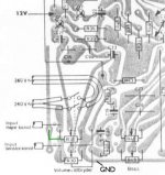
It's a narrow space to take photos around the volume pot. Brownish extension connected to the rear of the volume pot does not have legs to the board.
There's one terminal in each corner of the brownish extension (total of 4). It distributes the VAC 240 for the voltage selector, which locates in the rear of the unit. Basically brown and blue wires(soldered to the same terminal) in the left bottom corner provide voltage for the selector and the other two black and blue are GND soldered to the same terminal on the top left corner I think.
Actually I discovered the volume pot is 2x5 pins/legs, just adds to the amazement.
I added the photo of the diagram which represents the wiring of the preamp board. But as the leftmost line on the preamp board is going nowhere, one of the pins on the row have no function. I carried out this test with DMM continuity mode, where I would locate each pin to the board.
I just wonder how the service fixed the problem, since the unit wouldn't turn on before the service
So what you guess is I need to make room for a new button in case I want a proper on off button and I have a strong feeling the volume pot is the original pot in place by the looks of it.
Attachments
What I'm wondering is whether the repair you had done consisted of just shorting out the faulty pole of the switch. The switch is a double pole type which means it switches and isolates both live and neutral. I'm wondering if the 'repair' consisted of shorting out whichever side of the switch had failed.
The other row of pins could just be for mechanical stability, they are not used electrically.
The other row of pins could just be for mechanical stability, they are not used electrically.
Yes that would make perfect sense to me. The two terminals in the rear of the volume pot seem like once soldered, so these wires were once separated.
About stability, there's still difference on the board in the lines connecting the two rows of the pot, but anyway... The pot's busted and I think it's like you explained it.
I think you guys know a lot about audio circuitry on this forum and stuff related, so I thought to check this issue, if the service would just tell me what their parts dealer told them. Like, if there could be a tiny vintage shop in certain location selling selected spare parts to vintage amps which wouldn't be commonly well known.
I tried to find corresponding bulbs here from various local dealers, but all of them told me to go electrics shop. Obviously small screw-type bulbs are also vintage in these days All I found were bulbs with different base in that size.
I have replaced all the bigger caps for preamp and amp circuitry and now there are 9 in total of the 10uF old caps still on the board and most of them on the right channel circuit. Then smaller ones like set of 470nF and maybe two pairs of axial film caps. So maybe it's wise to replace the 10uF caps at least as I'm here doing this.
Then there are like 5 bigger caps, which are originals, sitting on the power supply board. Maybe I should replace them as well, even if everything seem to work fine now and sounds are brilliant. Biggest of them is 500uF. Should I be more careful on selecting replacements concerning voltage ratings or is power supply board part of the "audio circuitry" as I learnt?
About stability, there's still difference on the board in the lines connecting the two rows of the pot, but anyway... The pot's busted and I think it's like you explained it.
I think you guys know a lot about audio circuitry on this forum and stuff related, so I thought to check this issue, if the service would just tell me what their parts dealer told them. Like, if there could be a tiny vintage shop in certain location selling selected spare parts to vintage amps
which wouldn't be commonly well known.I tried to find corresponding bulbs here from various local dealers, but all of them told me to go electrics shop. Obviously small screw-type bulbs are also vintage in these days
All I found were bulbs with different base in that size.I have replaced all the bigger caps for preamp and amp circuitry and now there are 9 in total of the 10uF old caps still on the board and most of them on the right channel circuit. Then smaller ones like set of 470nF and maybe two pairs of axial film caps. So maybe it's wise to replace the 10uF caps at least as I'm here doing this.
Then there are like 5 bigger caps, which are originals, sitting on the power supply board. Maybe I should replace them as well, even if everything seem to work fine now and sounds are brilliant. Biggest of them is 500uF. Should I be more careful on selecting replacements concerning voltage ratings or is power supply board part of the "audio circuitry" as I learnt?
Bulbs will be a problem in finding replacements. If you look at the full circuit diagram they are shown as three bulbs wired in parallel across a winding on the transformer. Measuring the voltage (AC volts) across bulb holder contacts will give a starting point for voltage required. You might find some car panel light bulbs suitable although you might need to add a resistor to drop voltage. Always ways and means though. Do the old bulbs have any markings for voltage and current ?
All the electros need replacing on something this age but films and such like will all be fine. Always replace with at least the same voltage rating (or higher). 500uf will be 470uf in todays money.
There are one or two vintage forums around where you could ask about a pot but tbh I think its a lost cause finding an original replacement.
UK Vintage Radio Repair and Restoration Discussion Forum
If the pot itself is faulty (and not just the switch) then all you can do is fit a conventional type and use the tone controls manually to compensate for the loudness omission. And that's all the loudness feature is, an alteration of the bass and treble at low level.
Yes, they do. 10V 0.2A. I will check for new bulbs from the electrics dealer on monday. Now they closed for the weekend.Do the old bulbs have any markings for voltage and current ?
Local dealer told me that type of bulb is common in flashlights and I checked them all from car parts to flashlights. I hope to find these from electrics dealer.
If that's still no avail, I'll make that tip work later on.
I think you're right about the pot and I consider it's probably waste of time trying to find new replacement. I'll have to think of an alternative way to fix it, like a new switch or button and route wiring from that brownish extension from the rear of the pot to the switch and back.
Now you probably come to think how I operate the unit. Ever since the amp was serviced for this problem I've been using unit with extension power cord with a switch, which is hidden behind the computer monitor and admit would be far more convenient to have on/off switch straight in the front panel of the unit. Anyway working here from hour to another, it's not that big deal to operate that power cord switch say twice a day.
Anyway you've been really helpful. I'm really greatful for that.
Now have a great weekend there.
Thanks and you too.
Bulbs... you'll have to search supplier catalogues (I'm not well up in miniature bulb sizes and what they are called) but there seem to be lots available.
These are in the right ballpark voltage and current wise, you would hve to measure the size and I've no idea on the thread.
W1309 - SLI EBT - 12V FILAMENT LAMP (10MM) 11 LUMEN | CPC UK
try a search under the 'miniature sub miniature filament lamps'
Miniature / Sub-Miniature Filament Lamps | CPC UK
and you too.Bulbs... you'll have to search supplier catalogues (I'm not well up in miniature bulb sizes and what they are called) but there seem to be lots available.
These are in the right ballpark voltage and current wise, you would hve to measure the size and I've no idea on the thread.
W1309 - SLI EBT - 12V FILAMENT LAMP (10MM) 11 LUMEN | CPC UK
try a search under the 'miniature sub miniature filament lamps'
Miniature / Sub-Miniature Filament Lamps | CPC UK
Hey this is exactly what I am looking for. Almost by the looks of it. First I will check from local electronics dealer, do they have any in stock.
As I am pondering on what to choose for replacements for the rest of the 10uF caps. Should I go with same make or is it any difference to go with other brand? Perhaps it would be silly to have caps from one brand on left channel and different brand on right channel circuit.
I decided to go with Vishay components as I read from one of the vintage restoration guides that it's a good brand. It looks like that there's better availability for other brands. Basically all the replacements I chose came from Farnell catalog and I should wait another week or more to get them in case I wanted to choose from there. Another option is to search Ebay, but there's limited stock available and order takes maybe a week too.
Ok, maybe I should just chill and get the Vishay parts anyway, would look coherent on the board.
Would it be any improvement to sound, if I replaced the speakers from basic Sony to say Wharfedale with this amp. I think I should probably upgrade the speaker cables then as well. Just for an opinion?
Would that seem like racing wheels fitted on mini cooper (no gain, just looks) or here we have that proverb fitting precious wood wheel to Lada won't give you any better ride
You would need to be sure on the bulbs as there are many variations, a bit like matching a box of old nut and bolt thread sizes. The company CPC is part of Farnell so they should all be listed there as well.
Its probably more of a feel good factor having matching parts left and right on something like this, performance wise there will be zero difference. Upgrading speakers would make a massive difference. Just try using the unit on a pair costing £$€1000 or 2000 and then tell me its not worth it Speaker cable would make little if any noticeable difference here as long as you are not trying to drive 50 or 100 metres of thin stuff. Long and thin = higher resistive loss. If its just 3 or 4 metres then 5 amp lamp flex would be a as good as anything.
Its probably more of a feel good factor having matching parts left and right on something like this, performance wise there will be zero difference. Upgrading speakers would make a massive difference. Just try using the unit on a pair costing £$€1000 or 2000 and then tell me its not worth it
Speaker cable would make little if any noticeable difference here as long as you are not trying to drive 50 or 100 metres of thin stuff. Long and thin = higher resistive loss. If its just 3 or 4 metres then 5 amp lamp flex would be a as good as anything.I'll compare the bulb with new before buying. Easy to compare when you have them side by side.
Man comes to think of new improvements, when some of the music you listened to earlier sounded pretty okay and after restoration process you can hear details of which you didn't hear before. Makes you want to believe there's more. What else I can bring out of them with better equipment.
Man comes to think of new improvements, when some of the music you listened to earlier sounded pretty okay and after restoration process you can hear details of which you didn't hear before. Makes you want to believe there's more. What else I can bring out of them with better equipment.
A recap is about as far as you can go realistically but you would gain from using better speakers.
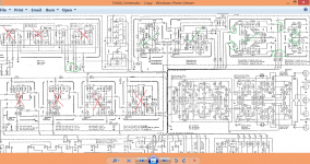
Don't be tempted to replace any caps in the tuner section apart from electrolytics on the rails. The drawing seems to show that most of the circuitry is in 'cans'. Don't even move any parts in those cans as the alignment of the tuner will alter due to stray capacitance between adjacent items changing .
Don't be tempted to replace any caps in the tuner section apart from electrolytics on the rails. The drawing seems to show that most of the circuitry is in 'cans'. Don't even move any parts in those cans as the alignment of the tuner will alter due to stray capacitance between adjacent items changing .
That's a good tip.
Actually tuner is useless for me at this point. I'm using this unit for computer media playback. These 'cans' are so called "Transmoduls". In the beginning I had big trouble realizing do these "cans" actually contribute to the left channel weakness, since one of the transmoduls handle stereo sound for tuner I think. I tested softly (there are 9 of them sitting side by side on the tuner board), if they're firmly seated and two of them appears to give room for little movement. I had thought, that if one of them is related to the problem it's going to be impossible to replace them. There are no new Transmoduls available.
You know it was all mess for me, being beginner with all this, trying to realize from circuit diagram what's related to the problem and what's not.
I went on testing tuner section and tuner seems to work fine. Actually the stereo signal bulb is the only bulb, which lights on currently in the unit, when I find stereo signal.
Must add to the earlier post, that suddenly have the feeling that most of the songs I listened to, which I presumed good sounding tunes are now just a good memory. There are some older recordings that sound worse now that I got the idea of far superior audio output
Tomorrow I will ask around for the smaller caps and bulbs and place order for replacements, if there's no stock available.
I suppose finding that old recordings don't sound as good as better modern ones is a hazard of the audio game
If the tuner is working OK then leave it all be, however there are some caps that could be replaced. The modules I marked in red I would leave alone although there are some electros in these to decouple the supply. Unless you could be sure of not disturbing or moving other parts in the can then I would leave them. The ones in green can be safely worked on as there is no RF (radio frequency) alignment in those.
If the tuner is working OK then leave it all be, however there are some caps that could be replaced. The modules I marked in red I would leave alone although there are some electros in these to decouple the supply. Unless you could be sure of not disturbing or moving other parts in the can then I would leave them. The ones in green can be safely worked on as there is no RF (radio frequency) alignment in those.
Attachments
Thanks for the additional effort on pointing out tuner caps.
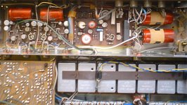
Here's blurry shot from above the unit case open, before recapping.
Tuner board is very narrow with Transmoduls side by side and I can see just two axial caps on the board.
I think those caps may locate in between the Transmoduls or hidden beneath them. It could be also that I don't have those caps at all here, since my unit would support only FM band. Schematics are for sister model, but some of it deals with my model as well.. schematics are bit confusing as we realized already
Moreover when I put the unit upside down tuner board is only halfway exposed, unlike power supply and amp boards. It means I would have to remove stuff before getting good access to certain parts of the tuner board, at worst desolder wiring temporarily to get access there.
Anyway I saved the file to my computer where you marked the easy caps.
Appreciate the effort, really!
Attachments
Late last night I finished with soldering the replacements 10uF caps.
Sounds great now.
Also replaced the two caps on the power supply board with 25uF capacity. One of them was dried out. I just wonder what difference did it make. Slim to none. On the power supply board I can see various terminals among 36V exit terminal, which most obviously feeds the preamp and amp boards. I just wonder, if there's any function for the rest of the various power terminals. Could it just be that power supply board is universal and there's function for them only on sister models.
I got the replacement bulbs. Bulb is standard E10 screw base. New bulbs are 12V, which means they are not as bright as 10V bulbs, but expecting longer life span. I searched around for 10V bulbs and they're not so common to find. This is all fine with me.
It was funny thing, getting the bulbs in place and switching power on bulbs wouldn't light up and then further checking proved a blown fuse. It was a bit of running around, but now I can say everything seem like in mint condition.
Thanks for the support.
I suppose its possible there could be unused terminals for distributing power to other models. The two 2000uf reservoir caps on the power supply would definitely be ones to replace though.
Bulbs will last much much longer on a lower voltage. eg. 1000hrs @ 12v, 2000hrs @ 11v perhaps 5000hrs @10v, 15000hrs @say 8 volt. That kind of scale.
Sounds like you have done a good job on it all Should be good for another 30 yrs or more.
Bulbs will last much much longer on a lower voltage. eg. 1000hrs @ 12v, 2000hrs @ 11v perhaps 5000hrs @10v, 15000hrs @say 8 volt. That kind of scale.
Sounds like you have done a good job on it all
Should be good for another 30 yrs or more.The two 2000uf reservoir caps on the power supply would definitely be ones to replace though.
The big caps were the first ones I replaced, which restored overall output power to the amp.
Yea, I suspect the rest of the power terminals are unused, since everything works fine among tuner.
Now that I got this fixing thing going, I should get something else to fix
Hey,
forgot to ask, since now everything's working well, that are there easy methods to shield the amp better from cell phone interference?
Like should I shield the speaker cables better or something?
See, now it amplifies so well that sometimes it picks up heavy interference
That didn't bother me before the recap, but now it's loud.
- Status
- This old topic is closed. If you want to reopen this topic, contact a moderator using the "Report Post" button.
- Home
- Amplifiers
- Solid State
- Troubleshooting stereo amplifier