Hi Richard,
You can buy ovenized oscillators. 10 MHz being the most common, and I do know of a source for oscillators for CD players. You can even get them locked to the GPS (which is actually inferior to a standard ovenized oscillator). With the 10 MHz oscillator you can use DDS technology to arrive at your specific frequency. Note that short term stability is the most important factor as long term drift will be a tiny amount worst case. With drift rates around 5 X 10e-9, there isn't very much to worry about here.
For a real blast, commercial ICs are made for the express purpose of cleaning up clocks. Although with an ovenized crystal oscillator, you should be at the level of a cleaned clock source. No advantage.
-Chris
Hi Brad,
Hi OS,
Using the lowest amount of drive current that will also reliably start the oscillator will give you the best short and long term stability. An S-C cut crystal running in an oven set to its particular turn-over temperature will give you the most stable frequency and drift figures. You can dive into all kinds of metrics, like Allen Deviation, but at this level and compared to the factory crystal, it would be a complete waste of time.
You could use a GPS disciplined ovenized x-tal oscillator, but you would want to put it into "hold-over" mode whenever you are playing music. This gives you a frequency almost traceable to NIST while maintaining an extremely low drift rate. This should give you a frequency error in the neighborhood of 5 X 10e-11 or better. This is just so far beyond accuracy needs that the frequency error of the original equipment used to create the CD in the first place would be by far the greatest error source. Never mind the fact that no one could hear any difference between the GPS locked oscillator to the ovenized oscillator free to drift. Any drift would still track ambient temperature changes.
This brings up another point. You would need to tightly control the temperature around your equipment. Not only do frequencies drift, but anything that is mechanical expands and contracts. There will be other things that change with temperature shifts. That knowledge ought to keep some folks up at night! Imagine how much the optics in the laser head assembly change - and they do change.
Try to keep your efforts in the realm of reasonable stability.
-Chris
Holly .. I am impressed! You broke a low frequency tuning fork???! Wow. How many amperes was the drive level at?I was rewarded once with a distinctly audible clink noise when I overdrove a tuning fork crystal.
Hi OS,
Using the lowest amount of drive current that will also reliably start the oscillator will give you the best short and long term stability. An S-C cut crystal running in an oven set to its particular turn-over temperature will give you the most stable frequency and drift figures. You can dive into all kinds of metrics, like Allen Deviation, but at this level and compared to the factory crystal, it would be a complete waste of time.
You could use a GPS disciplined ovenized x-tal oscillator, but you would want to put it into "hold-over" mode whenever you are playing music. This gives you a frequency almost traceable to NIST while maintaining an extremely low drift rate. This should give you a frequency error in the neighborhood of 5 X 10e-11 or better. This is just so far beyond accuracy needs that the frequency error of the original equipment used to create the CD in the first place would be by far the greatest error source. Never mind the fact that no one could hear any difference between the GPS locked oscillator to the ovenized oscillator free to drift. Any drift would still track ambient temperature changes.
This brings up another point. You would need to tightly control the temperature around your equipment. Not only do frequencies drift, but anything that is mechanical expands and contracts. There will be other things that change with temperature shifts. That knowledge ought to keep some folks up at night! Imagine how much the optics in the laser head assembly change - and they do change.
Try to keep your efforts in the realm of reasonable stability.
-Chris
But, in this case what is the most likely #1 jitter bug to fix and how?
THx-RNMarsh
DAC-originating jitter?
Jan
The causes in a home system and the cures, if any. Got specific info for improvements? I go from A to Z and sort things out. But, in this case what is the most likely #1 jitter bug to fix and how?
THx-RNMarsh
In the hotel so limited recourses, there all on my serious laptop (work one). My own view on jitter is firstly actually determining if there is a problem and how severe it is.
My view on solving it with add on cards with clocks on them has been aired before, most times its a joke and will only make matters worse, if not done correctly and a lot (most) aren't.
That said looking at the boards in a lot of CD players, cost has been the factor, signal integrity an after thought...if at all.
I believe jitter has become another audiophile gremlin and an emotive issue, there needs to be proper measurement done but this is beyond most of us so its mostly speculation...
So I stream wirelessly from HD (because its easier and I perceive it sounds better) and don't worry about jitter, I just enjoy the music.
")
I will dig out my jitter stuff as we do worry about it for some interfaces....a bit faster than SPDIF though.
Layout, critical with clock signals....
An add on board with silly long leads, especially where only one lead is used (GND) being provided by the supply connections, don't improve things. That's why on most designs the clock is next to a device it feeds or a clock distribution device is used, I always simulate distributed clocks using the actual layout for signal integrity.
Anantech has already mentioned BIG crystals sealed temp controlled environment....
Decoupling for oscillators if you use them is critical, best results using a largish X7R with a very small value COG next to the pins, values determined by frequency etc, and a good PSU, preferably its own LDO next to the device.
there needs to be proper measurement done but this is beyond most of us so its mostly speculation...
So I stream wirelessly from HD (because its easier and I perceive it sounds better) and don't worry about jitter, I just enjoy the music.
I will dig out my jitter stuff as we do worry about it for some interfaces....a bit faster than SPDIF though.
I do something similar -- and dont worry about CD jitter any more. I do have the dedicated jitter analyzer on its way to me. I like to correlate measurements with what i can hear.
I have some test equipment that use an internal xtal osc ... such as a freq counter/TIM and it's internal 1-10MHz is brought out to the rear BNC. Maybe some of those instruments will be very jitter free.... but will test first.
THx-RNMarsh
Last edited:
In the 70's and 80's Philips had a tie up with Matsushita and they worked on all sorts of things together. At various points they worked with nearly all the big names in Japan - Sony was the most fanous though.
From my years of working with Philips, I know their corporate culture was that they, as a big company, will speak only with other big companies. Their most famous collaberation was with Sony over the Red Book CD, but as Andrew noted, they wurked with others as well.
The reason why I believe that the Black Tulip series was actually produced by Mitsubushi is simple, bur also possibly wrong - the insides consist of Mitsubishi badged transistors and ICs, werever possible. There are other people's components as well, of course, but Mitsubishi absolutely dominates.
However, I feel it's much more important who actually desiged it, more so than who actually makes it. The tuner is typical of the Japanese industry of the day, but the preamp is not. For a start, it is a fully complementary affair from input to output, which was not typucal of the Japanese products of the day. And they really went to town on the whole series, with Noble and TKD pots inside, high quality components all over the place, way better than usual RCA connectors at the back.
The most intriguing component are the power amps. I have the smaller one, RH370, rated at 60 WPC, and there's a bigger one, RH380, rated at 100 WPC. They are exactly the same, except that the bigger model has not one, but two pairs of output devices. The circuit design is generally the one which appeared there, and would be used in Marantz amplifiers for years after that, in general and in circuit details. It looks like nothing Philips had ever done by that time and was not used in Philips and sister companies (Grundig, Loewe Opta) after that.
Anyway, good for those times, lavishly done as never again, but by current standards, it's just good and no more than that. Which is not bad, given that they ceased production by 1983, i.e. after they took over Marantz and obviously didn't want any in-house competition.
Last edited:
My words ;-)Layout, critical with clock signals....
An add on board with silly long leads, especially where only one lead is used (GND) being provided by the supply connections, don't improve things. That's why on most designs the clock is next to a device it feeds or a clock distribution device is used, I always simulate distributed clocks using the actual layout for signal integrity.
This said, i had made some measurements on my DCX2496 when i had modified-it. Changing Power supply for low noise everywhere was a huge improvement. Changing the clock, not at all. That, i suppose, because the RFI and other pollutions added to this new clock was worse than the jitter of the original clock.
How much direct, 'hands on' experience with CD clock modifications do you have?I have been commenting on this on many clock modification threads, considering how critical clocks are it breaks my PCB heart to see the poor signals being abused so.....
I do something similar -- and dont worry about CD jitter any more. I do have the dedicated jitter analyzer on its way to me. I like to correlate measurements with what i can hear.
I have some test equipment that use an internal xtal osc ... such as a freq counter/TIM and it's internal 1-10MHz is brought out to the rear BNC. Maybe some of those instruments will be very jitter free.... but will test first.
THx-RNMarsh
The more I have looked into jitter in Audio the more perplexed I have become, just trying to define a base figure for jitter to work on is fraught with one-downmanship with ever decreasing claims of what is audible, I think we are at 5 femtoseconds now
How much direct, 'hands on' experience with CD clock modifications do you have?
Wrong question, try
How much experience do you have with clocks for:
Frequency hopping communications...
High speed designs....
High speed analogue digital conversion...
Audio analogue digital and analogue convertor clocks (professional)...
clocks on every digital board I do....
ETC..
Many years of practical experience of seeing and fixing what happens when clock distribution goes wrong...
Forgot to add, many hours simulating clock layouts and termination schemes to get the best signal integrity, all verified with measurements....
Now your point is?
Last edited:
My point is that, before you make comments from the 'high up in the industry' bla bla, 'I know better', 'see my medals' and so on, you should at least once get your sleeves up and try it in practice.Now your point is?
Do clock modifiers get it wrong in clock distribution, radiation, noise pick-up etc. departments? Yes, sometimes. Despite all this, do they get improvement in percieved sound quality with their clocks? Yes, most of the time.
To me that is 'mission accomplished', there's no need to bash them for not following aerospace industry practices.
Last edited:
My point is that, before you make comments from the 'high up in the industry' bla bla, 'I know better', 'see my medals' and so on, you should at least once get your sleeves up and try it in practice.
Do clock modifiers get it wrong in clock distribution, radiation, noise pick-up etc. departments? Yes, sometimes. Despite all this, do they get improvement in percieved sound quality with their clocks? Yes, most of the time.
To me that is 'mission accomplished', there's no need to bash them for not following aerospace industry practices.
You are a bit sad mate....
I'm sorry but on those threads I actually give practical advice on how to improve what they are doing to get the best signal integrity....
At the end of the day trying to get the best signal integrity is what they are trying to achieve so giving them practical advise on how to do this is not bashing them. Nor is it aerospace practice, it best practice for EVERY design that relies on a clock to function.
So suck your attitude back in mate... maybe if you listened you might learn something from those willing to try and help where they can instead of your childish pathetic attitude....
As to rolling up my sleeves, I have already said I have many years experience in getting clock signals from A to B in many systems, clocks used for audio based digital systems and convertors are NO DIFFERENT from any other clock, and we also do pro audio gear.....
I still stand by the view that unless you are very careful the majority of clock mods may add to the problem not solve it.
Surely a clock mod has to add to the problem, as that is the best way to achieve a change in sound? Assuming the original designers were moderately competent there is not much scope for improvement - any genuine improvement will only change the sound by a tiny amount. There is huge scope for significant degradation, but if not obviously bad the tweaker will assume that a change is an improvement. It works for cables; why not clocks too?marce said:I still stand by the view that unless you are very careful the majority of clock mods may add to the problem not solve it.
Marc, have you seen the Oppo thread? That is really funny.
Yes...
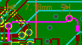
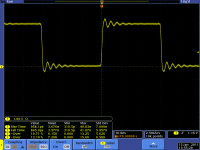
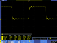
Anyway from up here in the high and mighty world of electronics are some screen shots and a picture of a layout showing even with slow clocks and short distances you can have problems. In this case the oscillator was driving directly into the resistor in the pack and going to the IC a few mm away. The problem was the drive strength of the clock signal, the plots show the effect of changing the series termination resistor value and its effect on the waveform.... I could get my hands dirtier but don't know whether I am worthy
as I have more such practical info.Attachments


Surely a clock mod has to add to the problem, as that is the best way to achieve a change in sound? Assuming the original designers were moderately competent there is not much scope for improvement - any genuine improvement will only change the sound by a tiny amount. There is huge scope for significant degradation, but if not obviously bad the tweaker will assume that a change is an improvement. It works for cables; why not clocks too?
Have you ever got your hands dirty.....
please no physics here, clock design by ear is the way to do it.....

- Status
- Not open for further replies.
- Home
- Member Areas
- The Lounge
- John Curl's Blowtorch preamplifier part II